


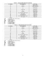


58
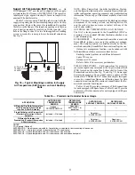
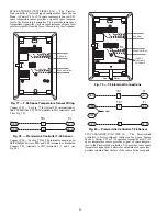
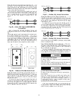
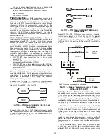
Fig. 86 — Space Thermostat Connections
If the 50TC-D16 unit has an economizer system and free-
cooling operation is required, a sensor representing Return Air
Temperature must also be connected (field-supplied and in-
stalled). This sensor may be a T-55 Space Sensor (see Fig. 81)
installed in the space or in the return duct, or it may be sensor
P/N 33ZCSENSAT, installed in the return duct. Connect this
sensor to TB3-1 and TB3-3 per Fig. 82.
CONFIGURE THE UNIT FOR THERMOSTAT
MODE — Connect to the CCN bus using a CCN service tool
and navigate to PremierLink Configuration screen for Operat-
ing Mode. Default setting is Sensor Mode (value 1). Change
the value to 0 to reconfigure the controller for Thermostat
Mode.
When the PremierLink controller is configured for Thermo-
stat Mode, these functions are not available: Fire Shutdown
(FSD), Remote Occupied (RMTOCC), Compressor Safety
(CMPSAFE), Supply Fan Status (SFS), and Filter Pressure
Switch (FILTER).
Economizer Controls
INDOOR AIR QUALITY (CO
2
) SENSOR — The indoor
air quality sensor accessory monitors space carbon dioxide
(CO
2
) levels. This information is used to monitor IAQ levels.
Several types of sensors are available, for wall mounting in the
space or in return duct, with and without LCD display, and in
combination with space temperature sensors. Sensors use infra-
red technology to measure the levels of CO
2
present in the
space air.
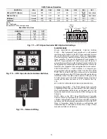
The CO
2
sensors are all factory set for a range of 0 to 2000
ppm and a linear mA output of 4 to 20. Refer to the instructions
supplied with the CO
2
sensor for electrical requirements and
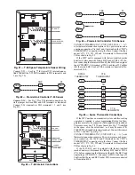
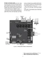
terminal locations. See Fig. 87 for typical CO
2
sensor wiring
schematic.
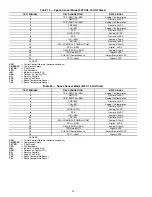
Fig. 87 — Indoor/Outdoor Air Quality (CO
2
) Sensor
(33ZCSENCO2)
—
Typical Wiring Diagram
To accurately monitor the quality of the air in the condi-
tioned air space, locate the sensor near a return-air grille (if
present) so it senses the concentration of CO
2
leaving the
space. The sensor should be mounted in a location to avoid di-
rect breath contact.
Do not mount the IAQ sensor in drafty areas such as near
supply ducts, open windows, fans, or over heat sources. Allow
at least 3 ft (0.9 m) between the sensor and any corner. Avoid
mounting the sensor where it is influenced by the supply air;
the sensor gives inaccurate readings if the supply air is blown
directly onto the sensor or if the supply air does not have a
chance to mix with the room air before it is drawn into the re-
turn airstream.
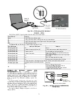
Wiring the Indoor Air Quality Sensor (Unit Sizes 08-14)
—
For each sensor, use two 2-conductor 18 AWG (American
Wire Gage) twisted-pair cables (unshielded) to connect the sep-
arate isolated 24 vac power source to the sensor and to connect
the sensor to the control board terminals.
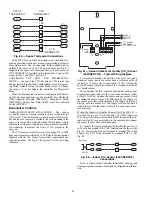
To connect the sensor to the control, identify the positive (4
to 20 mA) and ground (SIG COM) terminals on the sensor. See
Fig. 87. Connect the 4-20 mA terminal to terminal TB1-9 and
connect the SIG COM terminal to terminal TB1-11. See
Fig. 88.
Fig. 88 — Indoor CO
2
Sensor (33ZCSENCO2)
Connections
Refer to PremierLink Controller Installation, Start-up, and
Configuration Instructions, for detailed configuration informa-
tion.
G
J4-12
J4-10
J4-8
Y1
Y2
2
R
R
4
6
J4-6
J4-4
W2
C
8
10
C
SPACE
THERMOSTAT
CTB
THERMOSTAT
PL
W1
TB3
CTB
THERMOSTAT
8
7 6 5 4
3
2 1
2 1
H G 24 VAC
OR
24 VDC
NC
ALARM
RELAY
CONTACT
S
COM
NO
}
0-10VDC
S
IG COM
4-20mA
+
+
-
+ -
J
3
J4
S
EN
J5-5
J5-
3
COM
9
11
TB1
TB1
IAQ
S
en
s
or
PL
24 VAC
Содержание Carrier WeatherMaker 50TC A08 Series
Страница 4: ...4 Fig 2 Unit Dimensional Drawing Size 08 09 12 Units...
Страница 5: ...5 Fig 2 Unit Dimensional Drawing Size 08 09 12 Units cont...
Страница 6: ...6 Fig 3 Unit Dimensional Drawing Size 14 Unit...
Страница 7: ...7 Fig 3 Unit Dimensional Drawing Size 14 Unit cont...
Страница 9: ...9 Fig 4 Unit Dimensional Drawing Size 16 Unit cont...
Страница 13: ...13 Fig 8 Roof Curb Details Size 16 Unit...
Страница 33: ...33 Fig 62 Typical Humidi MiZer Adaptive Dehumidification System Humidistat Wiring 50TC 08 14 Unit Sizes...
Страница 34: ...34 Fig 63 Typical Humidi MiZer Adaptive Dehumidification System Humidistat Wiring 50TC 16 Unit Sizes HUMIDISTAT...
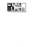
Страница 50: ...50 Fig 73 50TC 16 Control Box Component PremierLink Locations...
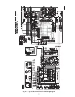
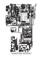
Страница 51: ...51 Fig 74 Typical PremierLink Control Wiring Diagram...
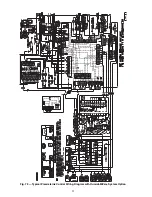
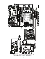
Страница 52: ...52 Fig 75 Typical PremierLink Control Wiring Diagram with Humidi MiZer System Option...
Страница 64: ...64 Fig 106 Typical RTU Open Controller Wiring Diagram 50TC 08 14 Size Units...
Страница 65: ...65 Fig 107 Typical RTU Open Controller Wiring Diagram 50TC 16 Size Unit...
Страница 66: ...66 Fig 108 Typical RTU Open Controller Wiring Diagram with Humidi MiZer System Option 50TC 08 14 Size Units...
Страница 67: ...67 Fig 109 Typical RTU Open Controller Wiring Diagram with Humidi MiZer System Option 50TC 16 Size Units...