


MINIMUM 12 IN.
TO COMBUSTIBLES
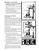
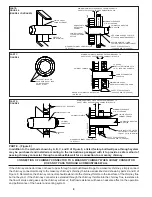
PART A, FIGURE 8
(FIGURE 5 CONTIUED ON NEXT PAGE)
1.
Use a minimum 3-1/2" thick brick masonry wall framed into the combustible wall. A fireclay liner (ASTM C315 or
equivalent) having a 5/8" minimum wall thickness must be used and it must be at least 12" away from any material
that could catch fire. The inside diameter of the fireclay liner shall be sized for the proper snug fit of a 6" diameter
chimney connector pipe. The fireclay liner shall run from the outer surface of the brick wall to, but not beyond, the
inner surface of the chimney flue and shall be firmly cemented in place. See Part A of Figure 8.
2.
Use a solid insulated listed factory-built chimney length having an inside diameter of 6" and having 1" or more of
solid insulation. There must be at least a 9" air space between the outer wall of the chimney length and any
combustible materials. The inner end of the chimney length shall be flush with the inside of the masonry chimney
flue shall be sealed to the flue and to the brick masonry penetration with nonwater-soluble refractory cement. Sheet
steel supports which are at least 24 gauge(0.024") in thickness shall be securely fastened to wall
surfaces on all sides. Fasteners between supports and the chimney length shall not penetrate the chimney liner.
See Part B of Figure 8.
3.
Use a 10" diameter ventilated thimble made of at least 24 gauge(0.024") steel having two 1" air channels. The venti-
lated thimble must be separated from combustible materials by a minimum of 6" glass fiber insulation. The opening
in the combustible wall shall be covered and the thimble supported with sheet steel supports which are at least 24
gauge (0.024") in thickness. The sheet steel supports shall be securely fastened to wall surfaces on all sides and
shall be sized to fit and hold the chimney section. Fasteners used to secure chimney sections shall not penetrate
chimney flue liner. See Part C of Figure 8.
4.
Use an 8" inside diameter solid insulated listed factory-built chimney length which has 1" or more of solid insulation.
The minimum length of this chimney section shall be 12" and will serve as a pass-through for the 6" diameter
chimney connector. There must be at least a 12" air space between the outer wall of the chimney section and any
combustible materials. The chimney section shall be concentric with and spaced 1" away from the chimney connec
tor by means of sheet steel support plates on both ends of the chimney section. The opening in the combustible wall
shall be covered and the chimney section supported on both sides with sheet steel supports which are at least 24
gauge (0.024") in thickness. The sheet steel supports shall be securely fastened to wall surfaces on all sides and
shall be sized to fit and hold the chimney section. Fasteners used to secure chimney sections shall not penetrate
chimney flue liner. See Part C of Figure 8.
5.
A listed factory-built wall pass-through system may be purchased and installed according to the instructions pack
aged with it to provide a safe method of passing the chimney connector through a combustible wall for connection
to a masonry chimney.
Additional requirements pertaining to Figure 8 and the above wall pass-through systems:
1.
Insulation material used as part of wall pass-through system shall be of noncombustible material and shall have a
thermal conductivity of 1.0 Btu • in./ft.² • °F (4.88 kg • cal/hr • m² • °C) or less
2.
All clearances and thicknesses are minimums: larger clearances and thickness are acceptable.
3.
A chimney thimble, as shown for 3" and 4" above (Parts C and D respectively of Figure 8) shall be for types "3" and
4" connections to facilitate removal of the chimney connector for cleaning. The chimney thimble shall be of ASTM
C315 fireclay with 5/8" minimum wall thickness , or material or equivalent durability. The inside diameter of the
thimble shall be sized for the proper snug fit of a 6" diameter chimney connector pipe. The thimble shall be installed
without damage to the chimney flue. The thimble shall extend through the chimney wall to, but not beyond, the
inner surface of the chimney flue and shall be permanently cemented in place with high temperature cement.
4.
A chimney connector to a masonry chimney, except for 2" above (Part B of Figure 8), shall extend through the wall
pass-through system to the inner face of the chimney flue, but not beyond. It does not have to be fastened in place
so long as it cannot accidently be pulled out of the chimney or shoved into the chimney flue. If fasteners are used
to secure the chimney connector to a masonry chimney, the fasteners shall not penetrate the chimney flue liner.
5.
Any material used to close up any opening for the connector shall be noncombustible.
CHIMNEY FLUE
MINIMUM CHIMNEY CLEARANCE TO
BRICK AND COMBUSTIBLES IS 2 IN.
MINIMUM CLEARANCES 12 IN.
OF BRICK ALL AROUND
CHINEY CONNECTOR TO
HEATER
FIRE CLAY LINER
(5/8" MIN. WALL THICKNESS)
MIN. 3-1/2" THICK BRICK
MASONRY WALL
MASONRY CHIMNEY
CONSTRUCTED TO
NFPA 211
7
Содержание LOGWOOD 2421
Страница 11: ...NOTES 11 ...


