Unitary products group HF-25 - 25 Ton Скачать руководство пользователя страница 10

278806-BIM-A-1106

10

Unitary Products Group

REFRIGERANT MAINS

Many service problems can be avoided by taking ade-
quate precautions to provide an internally clean and
dry system and by using procedures and materials that
conform to established standards.

Use hard drawn copper tubing where no appreciable
amount of bending around pipes or other obstructions
is necessary. If soft copper is used, care should be
taken to avoid sharp bends that may cause a restric-
tion.

Pack fiberglass insulation and a sealing material such
as permagum around refrigerant lines where they pen-
etrate a wall to reduce vibrations and to retain some
flexibility.

Support all tubing at minimum intervals with suitable
hangers, brackets or clamps.

Braze all copper-to-copper joints with Silfos-5 or equiv-
alent brazing material. Do not use soft solder.

Insulate all suction lines with a minimum of 1/2" ARMA-
FLEX or equal. Liquid lines exposed to direct sunlight
and/or high temperatures must also be insulated.

Never solder suction and liquid lines together. They
can be taped together for convenience and support
purposes, but they must be completely insulated from
each other.

The liquid and suction connections permit leak testing,
evacuation, and partial charging of the field piping and

the evaporator without disturbing the condenser coils
during initial installation.

Before beginning installation of the mains, be sure that
the unit has not developed a leak in transit. If pressure
still exists in the system, it can be assumed to be leak
free. DO NOT release the holding charge.

A filter-drier MUST be field-installed in the liquid line of
every system to prevent dirt and moisture from damag-
ing the system. Properly sized filter-driers are shipped
with each condensing section.

NOTE:

Installing a filter-drier does not eliminate the
need for the proper evacuation of a system
before it is charged.

A field-installed moisture indicating sight-glass should
be installed in the liquid line(s) between the filter-drier
and the evaporator coil. The moisture indicating sight-
glass can be used to check for excess moisture in the
system or used as a visual means to verify refrigerant
charge.

All lines have a copper disc brazed over the end. Also,
if the unit does not have service valves, the holding
charge must be reclaimed to allow the installer to con-
nect piping. The temperature required to make or break
a brazed joint is sufficiently high to cause oxidation of
the copper unless an inert atmosphere is provided.

NOTE:

Dry Nitrogen should flow through the system at
all times when heat is being applied and until
the joint has cooled.

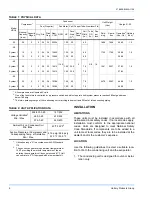
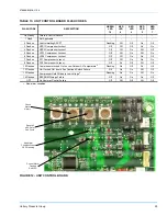
TABLE 5: ELECTRICAL DATA

Unit Model

Designation

Compressor

Fan Motor

Unit 

Ampacity 

(Amps)

Max. Fuse 

Size 

(Amps)

Min. 

Disconnect 

Size

Power Supply

Qty.

RLA

(each)

LRA

(each)

Power Supply

HP

Qty. FLA (each)

HF-25

2

208/230-3-60

2

47.1

350.0

208/230-3-60

1.25

4

4.5/4.3

124.6

150

150

4

460-3-60

2

25.0

158.0

460-3-60

1.25

4

2.15

64.9

80

70

5

575-3-60

2

19.9

125.0

575-3-60

1.25

4

1.7

51.9

70

60

HL-30

2

208/230-3-60

4

32.1

195.0

208/230-3-60

1.25

4

4.5/4.3

154.4

175

175

4

460-3-60

4

16.4

95.0

460-3-60

1.25

4

2.15

78.3

90

90

5

575-3-60

4

12.1

80.0

575-3-60

1.25

4

1.7

58.2

70

70

HL-40

2

208/230-3-60

4

42.0

239.0

208/230-3-60

1.50

4

5.8

201.7

225

225

4

460-3-60

4

19.2

125.0

460-3-60

1.50

4

2.9

93.2

110

110

5

575-3-60

4

13.8

80.0

575-3-60

1.50

4

2.2

67.5

80

80

HL-50

2

208/230-3-60

4

47.1

350.0

208/230-3-60

1.50

4

5.8

224.7

250

250

4

460-3-60

4

25.0

158.0

460-3-60

1.50

4

2.9

117.9

125

150

5

575-3-60

4

19.9

125.0

575-3-60

1.50

4

2.2

93.4

110

110

Содержание HF-25 - 25 Ton

Страница 1: ...NING Notes are intended to clarify or make the installation easier Cautions are given to prevent equipment damage Warnings are given to alert installer that personal injury and or equipment dam age ma...

Страница 2: ...PPROVAL 26 MAINTENANCE 27 CLEANING CONDENSER SURFACE 27 LUBRICATION 27 COMPRESSOR REPLACEMENT 27 LIST OF FIGURES Fig Pg 1 CORNER WEIGHTS CENTER OF GRAVITY 7 2 TYPICAL RIGGING 8 3 TYPICAL FIELD WIRING...

Страница 3: ...OF GRAVITY INCHES 7 4 MINIMUM CLEARANCES 8 5 ELECTRICAL DATA 10 6 SUCTION LINES 13 7 LIQUID LINES 14 8 R 22 LINE CHARGE 14 Tbl Pg 9 UNIT DIMENSIONS INCHES 18 10 PIPING AND ELECTRICAL CONNECTION SIZES...

Страница 4: ...onditioner Split System L Product Identifier F R 22 Standard Efficiency 2 Pipe L R 22 Standard Efficiency 4 Pipe 30 Nominal Cooling Capacity MBH 25 25 Ton 30 30 Ton 40 40 Ton 50 50 Ton C Heat Type C C...

Страница 5: ...properly REFERENCE This instruction covers the installation and operation of the basic condensing unit For information on the installation and operation of the evaporator blower units refer to instru...

Страница 6: ...8 1658 49 65 1 0 30 System 1 15 2 2 24 36 12690 1 25 25 60 1730 1790 30 08 1 0 System 2 15 2 2 24 36 12690 1 25 25 60 30 08 40 System 1 20 2 2 30 22 15414 1 50 32 5 78 1961 2037 37 83 1 0 System 2 20...

Страница 7: ...er pendicular to the roof joists 2 Extend beyond the dimensions of the section to distribute the load on the roof 3 Be capable of adequately supporting the con centrated loads at the corners See Figur...

Страница 8: ...ompressor out through the top of the unit RIGGING Exercise care when moving the unit Do not remove any crating until the unit is near the place of installation When preparing to move the unit always d...

Страница 9: ...oducing a high noise level the scroll is misphased CONTROL WIRING Route the necessary low voltage control wires from the Simplicity control board to the thermostat and also from the low voltage conden...

Страница 10: ...the system Properly sized filter driers are shipped with each condensing section NOTE Installing a filter drier does not eliminate the need for the proper evacuation of a system before it is charged A...

Страница 11: ...mage the valve seals Ensure the valve is ade quately protected prior to any brazing on the valve body Unbraze the sealing disk and prepare the joint for connections of the main lines Connect the lines...

Страница 12: ...be evacuated After proper evacuation and dehydration charge the required weight of liquid refrigerant into the liquid access connection After refrigerant flow slows start the compressor and continue t...

Страница 13: ...2 System 2 Full Capacity 15 47 1 3 8 2873 4 1 1 5 8 2030 1 8 2 1 8 1167 0 5 Half Capacity 7 5 23 5 1 3 8 1437 1 1 1 5 8 1015 0 5 2 1 8 850 0 2 HL 40 System 1 Full Capacity 20 64 1 5 8 3120 4 3 2 1 8 1...

Страница 14: ...5 8 440 13 2 7 8 212 2 3 1 1 8 90 0 6 System 2 Full Capacity 20 64 5 8 440 13 2 7 8 212 2 3 1 1 8 90 0 6 HL 50 System 1 Full Capacity 25 76 5 8 400 8 5 7 8 265 3 4 1 1 8 156 1 0 System 2 Full Capacit...

Страница 15: ...278806 BIM A 1106 Unitary Products Group 15 FIGURE 3 TYPICAL FIELD WIRING DIAGRAM HF 25 UNIT Note 1 Note 1 See page 16 and 17 for details on wiring HF HL models to non LF LL indoor models...

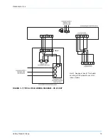
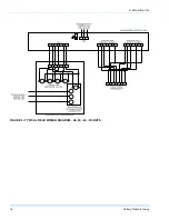
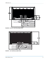
Страница 16: ...278806 BIM A 1106 16 Unitary Products Group FIGURE 4 TYPICAL FIELD WIRING DIAGRAM HL 30 40 50 UNITS...

Страница 17: ...els isolation relays must be installed to avoid overloading on 75 VA transformer on condensing unit Non LF LL units may not include any or all of the components required to wire the unit use the diagr...

Страница 18: ...t from the left or right side Electrical connections for power and control wiring is made from the front of the unit left of the electrical con trol box access See Tables 10 11 and 12 and Figures 7 th...

Страница 19: ...BIM A 1106 Unitary Products Group 19 FIGURE 7 25 30 40 TON POWER AND CONTROL WIRING CONNECTIONS Control Wiring Power Wiring FIGURE 8 50 TON POWER AND CONTROL WIRING CONNECTIONS Control Wiring Power W...

Страница 20: ...7 8 HOLE TABLE 11 PIPING AND ELECTRICAL CONNECTION SIZES 30 40 50T INCHES CONNECTION ENTRY SIZE SUCTION LINE SYS 1 1 5 8 OD LIQUID LINE SYS 1 7 8 OD SUCTION LINE SYS 2 1 5 8 OD LIQUID LINE SYS 2 7 8 O...

Страница 21: ...1106 Unitary Products Group 21 FIGURE 10 30 40 TON PIPING CONNECTIONS Liquid Sys 2 Suction Sys 2 Liquid Sys 1 Suction Sys 1 FIGURE 11 50 TON PIPING CONNECTIONS Liquid Sys 2 Suction Sys 2 Liquid Sys 1...

Страница 22: ...ectrical wire laying against a hot refrigerant line INITIAL START UP 1 Supply power to the unit through the disconnect switch at least 8 hours prior to starting the com pressor 2 Move the system switc...

Страница 23: ...ck out the associated compressor and flash an error code see Table 13 An ambient air switch will lock out mechanical cooling at 40 F In order to operate the unit in ambient temper atures below 40 F th...

Страница 24: ...es the compressors and condenser fans are de energized Otherwise the unit operates each cooling stage until the ASCD has elapsed Upon the completion of first stage cooling the blower is stopped follow...

Страница 25: ...ressor Lockout Off Off On Off On 6 Flashes LPS2 Compressor Lockout Off Off On On Off 7 Flashes FS1 Compressor Lockout Off Off On On On 8 Flashes FS2 Compressor Lockout Off On Off Off Off 10 Flashes Co...

Страница 26: ...art immediately upon a call for first stage cooling However fan two is equipped with a fan cycling switch and will not start until the sys tem head pressure reaches 280 psig Condenser fan two will ope...

Страница 27: ...ny maintenance COMPRESSOR REPLACEMENT Obtain replacement compressor or parts from your local Distributor FIGURE 14 25 TON CHARGING CHART 25 ton Charging Chart 100 150 200 250 300 350 400 60 70 80 90 1...

Страница 28: ...th the TXV s left to the factory setting If the TXV s have been adjusted in the field the chart above may no longer apply FIGURE 16 40 TON CHARGING CHART 40 ton Charging Chart 100 150 200 250 300 350...

Страница 29: ...harge Pressure PSI Outdoor Temperature 115 105 95 85 75 65 1 Ensure all condenser fans are running when charging unit One fan may shut down at lower ambient temperatures making the chart above inaccur...

Страница 30: ...278806 BIM A 1106 30 Unitary Products Group FIGURE 18 TYPICAL 25 TON CONDENSER UNIT WIRING DIAGRAM 208 230 3 60...

Страница 31: ...278806 BIM A 1106 Unitary Products Group 31 FIGURE 19 TYPICAL 25 TON CONDENSER UNIT WIRING DIAGRAM 460 3 60 575 3 60...

Страница 32: ...278806 BIM A 1106 32 Unitary Products Group FIGURE 20 TYPICAL 30 or 40 TON CONDENSING UNIT WIRING DIAGRAM 208 230 3 60...

Страница 33: ...278806 BIM A 1106 Unitary Products Group 33 FIGURE 21 TYPICAL 30 or 40 TON CONDENSING UNIT WIRING DIAGRAM 460 3 60 575 3 60...

Страница 34: ...278806 BIM A 1106 34 Unitary Products Group FIGURE 22 TYPICAL 50 TON CONDENSER UNIT WIRING DIAGRAM 208 230 3 60...

Страница 35: ...278806 BIM A 1106 Unitary Products Group 35 FIGURE 23 TYPICAL 50 TON CONDENSER UNIT WIRING DIAGRAM 460 3 60 575 3 60...

Страница 36: ...change without notice Printed in U S A 278806 BIM A 1106 Copyright 2006 by Unitary Products Group All rights reserved Supersedes 66410 035 19321 000 B 0404 Unitary 5005 Norman Products York OK Group D...

Отзывы: