Unitary products group G8C Скачать руководство пользователя страница 6

650.67-N2V

035-15881-402 REV. A (1199)

6

Unitary Products Group

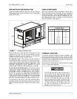
It is recommended that the supply air duct attached to the fur-
nace be provided with a removable access panel. The open-
ing should be accessible when the furnace is installed in
service and should be large enough that smoke or reflected
light may be observed inside the casing to indicate the pres-
ence of leaks in the heat exchanger. The cover panel for this
opening should be attached in such a manner as to prevent
leaks.

A/C USAGE DUCT SYSTEM

1.

When a single (common) duct system is used one of the 
following methods shall be used:

a.

The optional cooling coil designed for slide-in instal-
lation with this furnace, 

b.

A self-contained A/C unit must be in parallel with
and isolated from the furnace.

2.

If two duct systems are used as could be the case with a 
coil-blower or a self-contained A/C unit, the furnace and 
A/C unit should be controlled by a single combination 
heating and cooling thermostat which will prevent the fur-
nace and A/C unit from operating simultaneously.

RETURN AIR, FILTERS, AND DUCT 
CONNECTIONS

RETURN AIR TEMPERATURE

This furnace is designed to be operated in normal household
temperatures. The continuous return air temperature must
not be below 60 ºF or above 85 ºF.

FILTERS

Air filters of adequate size must be used with the return air
supply to this furnace. Failure to do so will cause dirt to accu-
mulate on the furnace blower motor, blower wheel, heat
exchanger and air conditioner coil, resulting in reduced sys-
tem efficiency, erratic control performance, and possible
equipment damage.

Filters are to be mounted at least one inch upstream from the
return connection to the unit. Locating the filter in a crawl
space, attic, or other inaccessible location will result in filters
not being changed as frequently as recommended.

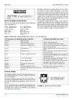
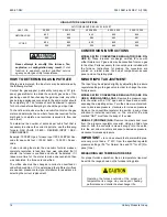
Size filters according to the requirements in Table 2.

DUCT CONNECTIONS

Although these units have been specifically designed for
quiet, vibration free operation, air ducts can act as sounding
boards and could, if poorly installed, amplify the slightest
vibration to the annoyance level.

Where the unit is located adjacent to the living area, the sys-
tem should be carefully designed with cold air strategically
located to minimize transmission through the return air grille.
Although this year-round air conditioner is designed with a
large blower operating at moderate speed, any blower mov-
ing a high volume of air will produce audible noise which
could be objectionable when the unit is located very close to
a living area. It is often advisable to carry the return air ducts
under the floor or through the attic. Such design permits the
installation of air return remote from the living area (i.e., cen-
tral hall).

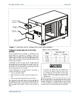
When installing duct outdoors where it will be exposed to
weather, care must be taken to completely weatherproof both
ducts and insulation. Take any additional measures, such as
flashings and caulking compound, necessary to provide a
good weather seal.

Dampers must be installed when a coil blower or
self-contained cooling unit is employed to prevent
conditioned cool air from coming in contact with
the heat exchanger to avoid moisture condensa-
tion and oxidation (rust), which could allow prod-
ucts of combustion to be circulated into the living
area by the furnace blower resulting in possible
asphyxiation. If dampers are the manually oper-
ated type, a means must be provided to prevent
either the furnace or the A/C unit from operating
(unless dampers are in full heat or cool position).

If a separate heating and separate cooling thermo-
stat is used, a manually operated electrical inter-
lock switch must be installed to prevent
simultaneous operation of both systems and avoid
a possible hazardous condition due to overheating
of the conditioned space.
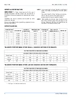
Table 2: 

FILTER REQUIREMENTS CHART

H

EAT

 I

NPUT


(BTU/HR)

C

OOLING


T

ONS


(N

OMINAL

R

ECOMMENDED

 M

IN

F

ILTER

 A

REA

:

Washable Type

Disposable 

Type

50,000-75,000

2.0-2.5

290

480

50,000-100,000

3-3.5

405

675

100,000-

125,000

4

460

765

125,000

5

580

965

Содержание G8C

Страница 1: ... AIR 4 INSTALLATION OF EXHAUST AND INTAKE AIR HOOD ASSEMBLIES 4 FURNACE SIZING AND DUCT SYSTEM DESIGN 5 A C USAGE DUCT SYSTEM 6 RETURN AIR FILTERS AND DUCT CONNECTIONS 6 RETURN AIR TEMPERATURE 6 FILTERS 6 DUCT CONNECTIONS 6 GAS PIPING 7 ELECTRICAL WIRING 8 SERVICE WIRING 9 ELECTRICAL GROUNDING 9 CONTROL WIRING 9 HEAT ANTICIPATOR 9 BLOWER MOTOR SPEED SELECTION 9 MOTOR TERMINAL IDENTIFICATION 10 BLO...

Страница 2: ...all safety rules SPECIFICATIONS BLOWER PERFORMANCE FOR SMALL CHASSIS OUTDOOR FURNACES BLOWER PERFORMANCE FOR LARGE CHASSIS OUTDOOR FURNACES See Figure 1 to determine chassis size CHASSIS SIZE BTUH INPUT BLOWER WHEEL SIZE TEMPERATURE RISE ºF CFM HIGH 0 5 W C MAX OUTLET TEMPERATURE ºF MOTOR HP Small Large X 50 000 10 x 7 30 60 1400 160 1 2 X 75 000 10 x 7 35 65 1400 165 1 2 X 100 000 10 x 7 45 75 14...

Страница 3: ...DARD TITLE 24CFR PART 3280 or when such stan dard is not applicable the STANDARD FOR MANUFAC TURED HOME INSTALLATION Manufactured Home Sites Communities and Set Ups ANSIA225 1 or the CAN CSA Z240 MH Series M86 Canadian Standard for Mobile Homes It is important to consult your local code authorities before installation is made The manufacturer assumes no responsi bility for equipment installed in v...

Страница 4: ... air hood See Figure 2 IMPORTANT This furnace is not to be used as a con struction heater to supply heat to an unfinished building dur ing the finishing phases of construction This practice exposes the furnace to abnormally low return air tempera tures which can cause condensation in the furnace or vent leading to premature failure This practice also exposes the furnace to an abnormally corrosive ...

Страница 5: ...educed overall operating efficiency of the furnace The supply and return duct system must be of adequate size and designed such that the furnace will operate within the designed air temperature rise range and not exceed the max imum designed static pressure These values are listed in Table 1 Additional information values and data necessary for heat loss heat gain and duct system design may be foun...

Страница 6: ...s have been specifically designed for quiet vibration free operation air ducts can act as sounding boards and could if poorly installed amplify the slightest vibration to the annoyance level Where the unit is located adjacent to the living area the sys tem should be carefully designed with cold air strategically located to minimize transmission through the return air grille Although this year roun...

Страница 7: ... it is permissible to use a flexible corrugated metal gas connector for the last section of gas piping connected to the furnace gas valve If a flexible connector is used it must be certified to be in compliance with ANSI Standard Z21 24 or in Canada with Standard CAN1 6 10 When making the connection at the gas control valve use a wrench on the inlet side of the valve to prevent any possible twisti...

Страница 8: ...wiring plates may be removed or removed and reinstalled for different conduit sizes See Figures 4 and 5 During pressure testing of the gas supply piping system observe the following to avoid fire explo sion asphyxiation or damage to the appliance If test pressure is greater than 1 2 psig 3 48 kPa 14 w c the furnace and its individual shut off valve must be disconnected from the gas sup ply system ...

Страница 9: ...structions furnished with the thermostat and make connections to the unit as shown on the unit wiring diagram It is recommended that size 18 AWG wire be used HEAT ANTICIPATOR If the wall thermostat has an adjustable heat anticipator the setting should be 48 amps If any accessories are to be con nected to the furnace the heat anticipator setting may change Use a suitable ammeter to measure the actu...

Страница 10: ...y time See Figure 6 SHOCK HAZARD Be sure electrical power to furnace is turned off before changing motor speeds Three Speed Motors Four Speed Motors Orange Common Black High Blue Medium Red Low Orange Common Black High Blue Medium High Yellow Medium Low Red Low Table 3 SERVICING TROUBLESHOOTING CHART 115 VOLT MODELS OF DIAGNOSTIC FLASHES PROBLEM SYMPTOMS PROBABLE PROBLEM LOCATION S Steady Off Norm...

Страница 11: ...R TERMINAL COLOR OF SPEEDS CHASSIS SIZE COM HIGH MED LOW COM HIGH MED HI MED LO LOW ORANGE BLACK BLUE RED ORANGE BLACK BLUE YELLOW RED 3 3 3 3 4 4 4 4 4 SMALL SMALL SMALL SMALL LARGE LARGE LARGE LARGE LARGE FACTORY SET BLOWER SPEEDS MODEL HEAT COOL OF SPEEDS CHASSIS SIZE 50K 3 TON 75K 3 TON 100K 3 TON 75K 5 TON 100K 5 TON 125K 5 TON LOW HIGH HIGH LOW MED HI MED HI MED MED MED MED LO MED LO MED LO ...

Страница 12: ...s the ignition system will lock out for one hour The system will remain in lock out mode until the room thermostat is cycled off then back on or one hour has elapsed causing the furnace to try for ignition again 7 The elapsed time from the moment the room thermostat closes to when the burners light may be 20 35 seconds This delay is caused by 1 the time required for the vent blower to come to full...

Страница 13: ... RATE The maximum BTUH input capacity for each model is shown on the furnace rating plate and in the specification table This input must not be exceeded The input shown may be used in geographic areas where the elevation is from 0 to 2000 feet The BTU input depends on the calorific heating value of the gas orifice size and mani fold pressure Orifice sizes are based on gas values of 1050 BTU cu ft ...

Страница 14: ... the other Parts necessary for conversion are included with the furnace Instructions for making the conversion are printed on a label inside the burner compartment access panel and on the rating plate MINOR INPUT ADJUSTMENT The input may be adjusted slightly by adjusting the pressure regulator setting in the gas valve in order to change the man ifold pressure MODELS WITH CONVERTIBLE REGULATOR SEE ...

Страница 15: ... of the blower housing 3 Remove the two 2 sheet metal screws which connect the triangular mounting bracket to the cabinet side 4 Remove the sheet metal screws which attach the top blower mounting flange to the blower bulkhead panel 5 Lift the blower assembly up to clear the bottom offset mounting bracket and pull toward you to remove REPLACEMENT PARTS If necessary to replace any component part s i...

Страница 16: ...6 LIMIT SWITCH 7 BLOWER BRACKET 8 SENSOR ROD 9 BLOWER MOTOR 10 BLOWER WHEEL 11 FURNACE CONTROL 12 BLOWER MOTOR HANGER 13 BLOWER LIMIT SWITCH 14 RUBBER MOTOR MOUNTS 15 TRANSFORMER 16 TERMINAL BLOCK 17 HEAT EXCHANGER 18 CAPACITOR 19 ROLLOUT SWITCH 20 BURNER 21 GAS VALVE 22 GAS ORIFICE 23 EXHAUST VENT HOOD FIGURE 11 REPAIR PARTS LISTING BURNER ASSEMBLY 4 SECTION MODEL SHOWN EXHAUST VENT HOOD ASSEMBLY...

Отзывы: