background image

DEFROST SEQUENCE OF OPERATION

These heat pumps have a unique “ambient modified”
time-temperature defrost control that automatically adjusts to
changes in the outdoor temperature. The defrost control will
shorten the defrost initiation time periods above 35

°

F and will

extend the defrost initiation time periods below 35

°

F. The

control is factory set to defrost at 110 minutes (T3), but it can
be field adjusted to defrost at 80 minutes (T2) or 50 minutes
(T1) in areas with high humidity.

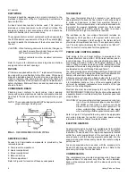
The curve in Figure 7 shows how defrost initiation times are
automatically compensated for changes in outdoor temperature.

EXAMPLE: If the timer is factory set on pin T-3 (110 minutes at
35

°

F outdoor) and the outdoor temperature climbs to 45

°

, the

time initiation cycle will decrease to every 100 minutes.

If the outdoor temperature drops to 10

°

F where ice is less likely

to form, the 110 minute interval will extend to every 150
minutes.

Two requirements must be met before a defrost cycle can be
initiated.

1. The defrost time cycle must be complete.

2. The liquid line temperature must be less than 28

°

F.

Defrost will terminate when the liquid line sensor reaches 55

°

F

or after 10 minutes. If both or just one circuit defrosts, electric
heat is energized.

The defrost time cycle will restart 10 minutes after the start of
the defrost cycle even though the liquid sensor terminated
defrost after 3 minutes.

During troubleshooting, the defrost time can be reduced to 20
seconds by shorting out the SW1 test pins on the module. The
pins are 1/2" long, 3/16" apart and are mounted on a white
base. See Figure 10.

LOCKOUT CONTROL

Any one of four conditions will put the system into a lock-out
condition during the heating or cooling mode:

1. The discharge line temperature reaches 255

°

F (215

°

F

reset) or,

2. The discharge pressure reaches 398 PSIG (310 PSIG

reset) or,

3. The suction line freezestat equals 26

°

F (38

°

F reset) or,

4. The low-pressure cut-out equals 7 PSIG (22 PSIG reset).

A lock-out will energize the emergency heat light on the
thermostat and the red LED light on the unit relay board.
Turning the thermostat switch to “Off” then back to “On”, will
reset the system.

NOTICE TO OWNER:

If a lockout occurs, check for the following problems before
calling a serviceman:

1. Dirty filters.

2. Snow accumulation.

3. Leaf or debris blockage.

After eliminating the problem, attempt to restart the system as
follows:

turn the system switch on the thermostat to its “OFF” position
for 10 seconds.

turn it back to its original position.

If the unit doesn’t start, call a serviceman.

NOTE: Models with an anti-recycle accessory will have a

5-minute delay before starting.

FIG. 7 - DEFROST INITIATION TIMES

511.06-N2W

12

Unitary Products Group

Содержание BCCB 090

Страница 1: ...s available in the following reference forms 530 18 N9 1V Electric Heater Accessory 530 18 N3 2V Economizer Accessory 530 18 N3 8V Motorized Outdoor Air Damper Accy 530 18 N3 9V Manual Outdoor Air Dam...

Страница 2: ...3 Physical Data 6 4 Point Loads 8 5 Supply Air Br Performance 9 6 Accessory Static Resistances 9 7 Blower Motor and Drive Data 10 8 Heat Anticipator Setting 11 9 Blower Motor Pulley Adjustment 11 FIGU...

Страница 3: ...is recommended to prevent mud splashing WARNING The unit should not be installed in an area where mud or ice could cause personal injury Remember that condensate will drip from the outdoor coil durin...

Страница 4: ...provide electric resistance heat only The compressors will not run The pilot light will indicate that the switch is on EM HT Nine conductors are required for this application POWER AND CONTROL WIRING...

Страница 5: ...4 1 7 1 5 8 130 64 52 2 3 1 3 1 3 5 7 2 6 2 1 7 5 3 4 2 7 42 0 21 1 17 7 43 8 21 9 18 3 50 25 20 50 25 20 120 208 230 3 60 460 3 60 575 3 60 16 7 17 3 9 6 8 3 150 73 62 3 5 2 5 2 5 7 5 3 4 2 7 10 6 4...

Страница 6: ...FINS PER INCH 15 13 FACE AREA Sq Ft 7 8 13 4 OUTDOOR FANS Two Per Unit PROPELLER DIA in 24 ea 24 ea FAN MOTOR HP 1 2 ea 3 4 ea NOM CFM TOTAL 2900 ea 4400 ea OUTDOOR COIL ROWS DEEP 2 2 FINS PER INCH 1...

Страница 7: ...ontrol Wiring Side 7 8 Bottom B 2 Power Wiring Side or Bottom Knockouts in the bottom of the unit can be located by the slice in the insulation UTILITIES ENTRY DATA RETURN AIR SUPPLY AIR OUTDOOR AIR O...

Страница 8: ...355 460 388 NOTE These weights are with economizer and 36 kW electric heat UNIT BCB 6 POINT LOADS LBS TOTAL A B C D E F 090 1 154 154 188 211 235 193 173 120 1 504 200 237 272 307 259 229 NOTE These...

Страница 9: ...2 62 2 45 0 92 2 91 2 72 1050 1 89 1 98 1 84 1 78 2 25 2 10 1 57 2 55 2 37 1 35 2 86 2 67 1 12 3 17 2 96 1090 2 08 2 12 1 97 1 97 2 41 2 24 1 78 2 72 2 54 1 55 3 06 2 86 MODEL BCB120 SIDE DUCT APPLIC...

Страница 10: ...compressors out when the suction line temperature drops below 26 F This is an automatic reset device HEATING SEQUENCE OF OPERATION The following sequence of operation is based on using a standard YOR...

Страница 11: ...filter access and the blower access panels as shown in Figure 4 2 Insert at least 8 of 1 4 inch tubing into each of these holes for sufficient penetration into the air flow on both sides of the indoo...

Страница 12: ...rost time cycle will restart 10 minutes after the start of the defrost cycle even though the liquid sensor terminated defrost after 3 minutes During troubleshooting the defrost time can be reduced to...

Страница 13: ...power to the unit to prevent personal injury FILTERS Inspect once a month Replace disposable or clean permanent type as necessary DO NOT replace permanent type with disposable MOTORS Indoor fan and ou...

Страница 14: ...511 06 N2W 14 Unitary Products Group...

Страница 15: ...511 06 N2W Unitary Products Group 15...

Страница 16: ...es 511 06 398 Subject to change without notice Printed in U S A Copyright by Unitary Products Group 1998 All rights reserved 511 06 N2Z Code SBL F 5005 York Drive Norman Oklahoma 73069 Unitary Product...

Отзывы: