background image


-


37


 -


WS

 Series

Advanced air conditioning systems


11.  CONTROL PROGRAMS and OPERATION INSTRUCTIONS 


11.1    General 


Protection:

  The  air  conditioner  is  protected  by  pressure  and  temperature  sensors.  The 

sensors cut off the unit once extreme and dangerous conditions are detected. The DISPLAY 
on the thermostat indicates the failure code as stipulated in the troubleshooting section. 
 

Restart after power failure: 

Back-up memory keeps the working data. Once power returns, 

the air conditioner will restart and return to its saved data. 
The  unit  can  be  modified  to  fail-safe  manual  restart  after  power  failure  (Start-Stop). 
Instructions for such modification are available upon request.  


Reset and restart after failure: 

Once the unit has stopped due to failure, restart is possible 

after  resetting.  Reset  the  system  by  pressing  ON/OFF  button  on  the  room  thermostat.  Call 
the technician for assistance should the failure be repeated. 

 
Restart time delay: 

Compressor starting time delay is 1 min. at first start and 3.5 min. before 

each restarting. Timer accuracy is ±20 sec. 
 

Evaporator  fan  control  (only  for  Heat  Pump  unit): 

In  cooling  mode  the  fan  runs 

continuously. In heating mode the fan stops running 15 sec. after compressor stop.  
 

Evaporator fan control (only for units with electrical heating elements):

 In cooling mode 

the  fan  runs  continuously.  In  heating  mode  the  fan  stops  running  40  sec.  after  the  heating 
elements are turned off. 
 

Water  temperature  control  (only  for  Heat  Pump  unit): 

Compressor  stops  if  water 

temperature  reaches  below  4ºC.  Compressor  restart  enabled  at  water  temperature  above 
10ºC.  Failure  in  water  temperature  sensor  does  not  stop  unit  operation.  If  failure  occurs  3 
times per hour and/or holds for 1 full hour, signal of failure 

ER8

 will appear stable and On/Off 

press for re-start not allowed. Re-start only by shut-off and switch-on of power supply. 
 

Heating  control  (only  for  units  with  electrical  heating  elements):

  The  return  air 

temperature sensor switches ON the first heating group at room temperature 1ºC lower than 
the set temperature. Heating is switched OFF at set point. 
Second  heating  group  is  switched  ON  at  room  temperature  2ºC  lower  than  the  set 
temperature. Second heating group is switched OFF at 1ºC under set point. 
 

Evaporator  coil  temperature  control:

  Compressor  stops  at  coil  temperature  below  0ºC. 

Compressor restart enabled at coil temperature above 8ºC. 
Failure in evaporator coil temperature sensor does not stop unit operation. 
 

Return air temperature sensor:


T

hermostats include an incorporated, build-in temperature 

sensing  element.  However,  an  external  sensor  (optional)  can  be  added.  In  such  case  the 
operation of the unit is governed by the selected sensor. 
The thermostat temperature setting range is 

16ºC 

to

 30ºC

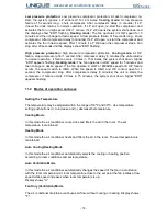
Failure in return air sensor will cause the compressor to run continuously. If unit was set to 
"AUTO" operation mode, the compressor will not run. 
 

Air-Flow  protection  (only  for  units  with  electrical  heating  elements):

  To  protect  the 

heating elements from overheating or from operating without flowing air.  
A  combination  of  differential  pressure  flow-switch  (for  heating  elements  larger  then  12KW) 
and temperature sensor immediately cut off the heating elements in case the temperature or 
air-flow  reaches  the  pre-set  protection  values.  The  fan  continues  running  for  additional  15 
sec. 


Содержание WS Series

Страница 1: ...Service Manual And Advanced air conditioning systems ...

Страница 2: ......

Страница 3: ...ER SOURCE CONSOLE UNITS 11 4 SPLIT CONDENSER UNITS 12 5 HEATING ELEMENT RECOMMENDATIONS 13 6 REFRIGERATION CYCLE DIAGRAMS 14 7 INSTALLATION INSTRUCTIONS 16 8 INSTALLING THE CONTROL SYSTEM AND CONNECTING POWER 22 9 ELECTRICAL WIRING DIAGRAMS 25 10 TROUBLESHOOTING GUIDE 31 11 CONTROL PROGRAMS and OPERATION INSTRUCTIONS 37 ...

Страница 4: ...r damaged Safety Signs Danger In plannig the location of the equipment take into consideration any areas that could present an unsafe situation Avoid power lines that could come into contact with the equipment Warning Electrical Safety To avoid electrical shock place equipment in a safe area use guards around control panels and always shut off and lock out control boxes when working on equipment I...

Страница 5: ...ized in applications such as residential industrial and commercial buildings offices schools and other facilities The operation of Unique WS air conditioners is quiet and durable with low maintenance requirements and provides efficient year round cooling and heating The units are suitable for cooling tower installations ground water sources or open water circuits Unique WS air conditioners feature...

Страница 6: ...conditioning systems 1 2 Manufacturing Options WS air conditioners are available in horizontal or vertical execution Standard layout includes SL SR FL and FR setup Additional configurations are available upon request FL FR SL SR ...

Страница 7: ...ample 400 3 50 400V 3 Phase 50 Hz COS φ Power factor for the unit FUSE Required fuse size Amp CAPACITORS μF Compressor capacitor Fan capacitor wherever applicable AIR FLOW m h Air Flow at High Speed in m h AIR FLOW cfm Air Flow at High Speed in cfm WATER FLOW m h Water Flow in m h WATER FLOW gpm Water Flow in gpm REFRIGERANT Type and Quantity of refrigerant charge Gr CAPACITY W Cooling capacity in...

Страница 8: ...3 17839 26721 35180 Heat Extraction Heating Watt 3211 4031 5647 7477 Btu h 10963 13762 19280 25525 Power Supply V Ph Hz 230 1 50 4 230 1 50 4 230 1 50 4 230 1 50 4 Time Delay Fuse Amp C10 C10 C16 C20 Water Piping in out BSP 3 4 3 4 3 4 1 Drain mm 19 19 19 19 Refrigerant Charge gr 1100 1100 1200 1300 Dimensions LxWxH mm 880x600x400 880x600x400 960x600x460 1040x600x460 Net Weight Kg 67 70 80 94 1 De...

Страница 9: ...8 17232 19715 21978 Btu h 45080 53626 58830 67307 75034 Heat Extraction Heating Watt 9292 10874 11982 14285 15180 Btu h 31723 37124 40907 48768 51825 Power Supply V Ph Hz 230 1 50 4 230 1 50 4 400 3 50 400 3 50 400 3 50 Time Delay Fuse Amp C20 C25 3xC16 3xC16 3xC16 Water Piping in out BSP 1 1 1 1 1 Drain mm 19 19 19 22 2 22 2 Refrigerant Charge gr 1500 1600 2300 2600 2700 Dimensions LxWxH mm 1090x...

Страница 10: ...ion Cooling Watt 27307 31065 37244 43601 52591 Btu h 93226 106056 127150 148855 179545 Heat Extraction Heating Watt 19201 22027 26231 30785 37716 Btu h 65554 75201 89551 105099 128763 Power Supply V Ph Hz 400 3 50 400 3 50 400 3 50 400 3 50 400 3 50 Time Delay Fuse Amp 3xC20 3xC25 3xC25 3xC40 3xC40 Water Piping in out BSP 1 1 1 1 1 Drain mm 22 2 22 2 22 2 30 30 Refrigerant Charge gr 3200 3700 3900...

Страница 11: ...14133 17839 26721 35180 Heat Extraction Heating Watt 3211 4031 5647 7477 Btu h 10963 13762 19280 25525 Power Supply V Ph Hz 230 1 50 4 230 1 50 4 230 1 50 4 230 1 50 4 Time Delay Fuse Amp C10 C10 C16 C20 Water Piping in out BSP 3 4 3 4 3 4 1 Drain mm 19 19 19 19 Refrigerant Charge gr 1100 1100 1200 1300 Dimensions LxWxH mm 1100x350x700 1100x350x700 1350x350x700 1350x350x700 Net Weight Kg 62 65 75 ...

Страница 12: ...350x420 3 8 5 8 1 61 WS 36 600x400x460 3 8 5 8 1 68 WS 43 650x450x520 1 2 3 4 1 68 WS 48 650x450x520 1 2 3 4 1 70 WS 54 650x450x520 1 2 3 4 1 71 WS 61 750x480x560 1 2 7 8 1 73 WS 75 750x480x560 1 2 7 8 1 75 WS 85 750x550x610 1 2 7 8 1 95 WS 102 750x550x610 1 2 7 8 1 100 WS 120 850x550x630 5 8 1 1 135 WS 144 1000x550x630 5 8 1 1 150 Data applicable for R410A For additional information contact Uniqu...

Страница 13: ... differ slightly from catalog Model Heating Element Kw 1 Ph Units 3 Ph Units Current Amp Fuse Amp Current Amp Fuse Amp WS 12 1 5 6 8 10 3x2 2 3x6 WS 15 2 9 1 10 3x3 1 3x6 WS 22 3 13 7 16 3x4 6 3x6 WS 28 4 18 2 20 3x6 1 3x10 WS 36 5 22 8 25 3x7 6 3x10 WS 43 6 27 3 32 3x9 1 3x16 WS 48 6 3x9 1 3x16 WS 54 8 3x12 2 3x16 WS 61 9 3x13 7 3x16 WS 75 9 3x13 7 3x16 WS 85 10 3x15 2 3x20 WS 102 12 3x18 2 3x20 ...

Страница 14: ... 14 WS Series Advanced air conditioning systems 6 1 Refrigeration Cycle Cooling Only ...

Страница 15: ... 15 WS Series Advanced air conditioning systems 6 2 Refrigeration Cycle Heat Pump ...

Страница 16: ...onduits having maximum overall diameters of 14 mm and 16 mm 23 mm in USA and Canada respectively Introduction of conduit or cable does not reduce clearances below 2 mm for basic supplementary insulation and 2 mm for functional insulation Supply cord shall not be lighter than each of the following a lower number in the code designation of the cord in IEC 60227 or IEC 60245 indicates a lighter type ...

Страница 17: ... mains must be incorporated in the fixed wiring in accordance with the national wiring regulations Important The control wires between the main control box and the wall mounted thermostat utilize low voltage 12V DC The supply mains cable and control wire flat cable between the wall mounted thermostat Alfa 261 and electrical box shall be passed in separate different ducts and not in proximity to ea...

Страница 18: ...al WS Installation Fig 7 1 1 Rubber Shock Absorbers 7 Control Unit 2 Strainer 8 Electrical cable 3 PTFE or Rubber ring 9 Acoustic Insulation 4 Flexible hose 10 Hanger Mounting Brackets 5 Cut Off Valves 11 Hanger Anchors 6 Rubber Joints Siphon T Connection and Drain Hose 12 Air Vent Plug ...

Страница 19: ...ket holes 10 Drill adequate holes and fix the long ceiling anchors 11 in position Lift up the unit onto the hanger anchors through the mounting brackets Insert four rubber shock absorbers on the four anchors as shown in Fig 7 1 Lock the assembly with the lock nut Should the unit be installed on a rigid surface stick four rubber absorbtion cushions on the four corners of the base In any mode of ins...

Страница 20: ... and open the two cut off valves 5 Allow water to flow in and out the unit Carefully open the air vent plug 12 Release all air from the system and close the plug back Inspect all connections for water leaks It is common practice to leave open the two cut off valves 5 throughout the rest of the installation and occasionally inspect the piping for leaks Fig 7 3 Flexible tube to water system 1 1 2 Do...

Страница 21: ... the Ducting Work To obtain optimal results duct cross sections connections elbows and branches must be properly designed We highly recommend seeking for expert advice on this matter Use flexible sleeve to connect the ducting to the air conditioner 7 8 Connecting the Temperature Sensor Bulbs See Fig 7 4 for identification The temperature sensor bulbs are factory pre assembled In case of replacemen...

Страница 22: ...located in the back part of the unit Push the back panel out Gently disconnect the data cable from its quick connect wiring harness Line the back panel up against the wall or against any other flat surface onto which it is to be mounted Drill holes and use appropriate fixing screws to fasten the panel to its location Locate the terminal box See Fig 8 2 and Fig 8 3 Complete the electrical connectio...

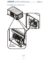
Страница 23: ... 23 WS Series Advanced air conditioning systems 8 2 Terminal Box Location Single Phase Unit Fig 8 2 ONL YFORUNIT S WIT HELECT RICAL HEAT ING ELEMENT S N GR ...

Страница 24: ... 24 WS Series Advanced air conditioning systems 8 3 Terminal Box Location 3 Phase Unit Fig 8 3 ONL YFORUNIT S WIT H ELECT RICAL HEAT ING ELEMENT S ...

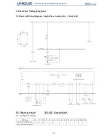
Страница 25: ...al Wiring Diagram Single Phase Cooling Only Model 260U HP High pressure control ALFA 123U Power switch unit LP Low pressure control ALFA 260U Room Thermostat CC Compressor contactor WS Type 12 15 22 28 36 43 48 54 61 75 85 102 120 144 MAIN POWER Cable Cross Section Area mm 2 5 2 5 2 5 4 4 6 ...

Страница 26: ...ooling Only Model 260U HP High pressure control ALFA 123U Power switch unit LP Low pressure control ALFA 260U Room Thermostat CC Compressor contactor WS Type 12 15 22 28 36 43 48 54 61 75 85 102 120 144 MAIN POWER Cable Cross Section Area mm 2 5 2 5 2 5 2 5 2 5 2 5 2 5 2 5 2 5 4 4 6 10 10 ...

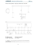
Страница 27: ...ing Elements Model 260U HP High pressure control CC Compressor contactor LP Low pressure control CH1 CH2 Heaters contactor ALFA 260U Room Thermostat TS1 TS2 Safety thermostat ALFA 123U Power switch unit WS Type 12 15 22 28 36 43 48 54 61 75 85 102 120 144 MAIN POWER Cable Cross Section Area mm 2 5 2 5 2 5 4 4 6 ...

Страница 28: ...l 260U HP High pressure control CC Compressor contactor LP Low pressure control CH1 CH2 Heaters contactor ALFA 260U Room Thermostat TS1 TS2 Safety thermostat ALFA 123U Power switch unit WS Type 12 15 22 28 36 43 48 54 61 75 85 102 120 144 MAIN POWER Cable Cross Section Area mm 2 5 2 5 2 5 2 5 2 5 2 5 2 5 2 5 2 5 4 4 6 10 10 ...

Страница 29: ... Phase with Heat Pump Model 260U HP High pressure control ALFA 123U Power switch unit LP Low pressure control CC Compressor contactor ALFA 260U Room Thermostat RV1 4 way valve WS Type 12 15 22 28 36 43 48 54 61 75 85 102 120 144 MAIN POWER Cable Cross Section Area mm 2 5 2 5 2 5 4 4 6 ...

Страница 30: ...Pump Model 260U HP High pressure control ALFA 123U Power switch unit LP Low pressure control CC Compressor contactor ALFA 260U Room Thermostat RV1 4 way valve WS Type 12 15 22 28 36 43 48 54 61 75 85 102 120 144 MAIN POWER Cable Cross Section Area mm 2 5 2 5 2 5 2 5 2 5 2 5 2 5 2 5 2 5 4 4 6 10 10 ...

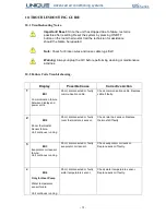
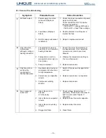
Страница 31: ...ble Cause Corrective Action 1 ER1 Communication failure between display and power units Short disconnected or faulty communication cable Check communication cable Replace cable if faulty 2 ER2 Room thermostat Sensor failure Unit continues running Short disconnected or faulty room thermostat air sensor Check return air sensor Replace thermostat if faulty 3 ER3 Evaporator coil sensor failure Unit co...

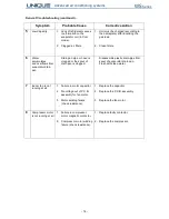
Страница 32: ...ation in heat exchanger 1 Clean strainer 2 Check cooling tower or the cooling water source for proper operation 3 a Check cooling tower or the cooling water source for proper operation b Heat exchanger is clogged Clean the heat exchanger or replace it 7 ER7 Only for units with electrical heating elements Heating elements protection 1 No air supply at indoor side 2 Indoor fan is not running 3 Air s...

Страница 33: ... is too high in Cool mode 3 Faulty compressor 1 Check if the room thermostat is on the desired mode If not select the correct mode refer to your User Manual 2 Observe the temperature setting on the room thermostat 3 Replace compressor 3 Only fan motor is working No cooling and or heating take place 1 Overload safety device on compressor is cut out due to high temperature 2 Compressor run capacitor...

Страница 34: ...n pan Drain pan pipe or hose is clogged or the spout of drain pan is clogged Disassemble plastic drain pipe from spout of evaporator drain pan Flush with clean water 7 Indoor fan is not running at all 1 Failure in motor capacitor 2 No voltage out of P C B assembly for fan motor 3 Motor winding failure check resistance 1 Replace the capacitor 2 Replace the P C B assembly 3 Replace the fan motor 8 C...

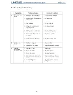
Страница 35: ...fective 1 Charge refrigerant gas 2 Recharge gas 3 Repair leakage 4 Replace strainer 5 Replace 4 Way valve 6 Replace solenoid 7 Replace compressor 2 Air circulation failure 1 Air filter is clogged 2 Air shutters are closed 1 Clean air filter 2 Open air discharge shutters 3 Freezing Conditions at Evaporator Coil 1 Clogged air filter 2 Faulty capacitor 3 Faulty fan motor 4 Air discharge shutters are ...

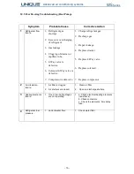
Страница 36: ...ctive 7 Compressor is defective 1 Charge refrigerant gas 2 Recharge gas 3 Repair leakage 4 Replace strainer 5 Replace 4 Way valve 6 Replace solenoid 7 Replace compressor 2 Air circulation failure 1 Air filter is clogged 2 Air shutters are closed 1 Clean air filter 2 Open air discharge shutters 3 Heating elements failure 1 One or two hating stages are not operating 1 a Check electrical heating elem...

Страница 37: ...temperature above 10ºC Failure in water temperature sensor does not stop unit operation If failure occurs 3 times per hour and or holds for 1 full hour signal of failure ER8 will appear stable and On Off press for re start not allowed Re start only by shut off and switch on of power supply Heating control only for units with electrical heating elements The return air temperature sensor switches ON...

Страница 38: ...perates in LOW speed for 5 minutes and then change to desire speed If the fan operate in LOW or MEDUM speed and H P failure occurs the speed switch to HIGH When fan speed is HIGH and H P contact open for 1 second the compressor stop After compressors delay 3 minutes the unit re starts the compressor If failure occurs 3 times in 15 minutes the system shut down Signal ER6 appears flashing 11 2 Modes...

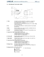
Страница 39: ...ng 5 Active Cool LED Cooling operation indicator LED LED ON indicates that the unit is cooling LED Blinking indicates delayed cooling action LED OFF indicates no cooling demand 6 Cooling LED This LED is ON in cooling and in Auto modes In the rest of the modes the LED is OFF 7 Heating LED This LED is ON in heating and in Auto modes In the rest of the modes the LED is OFF 8 Active Heat LED Heating o...

Страница 40: ... 40 WS Series Advanced air conditioning systems NOTES NOTES NOTES NOTES ...

Страница 41: ......

Страница 42: ...Unique Engineering Air Conditioning Mitzpe Sapir Industrial Park P O B 13201 Tsur Igal 44862 ISRAEL Tel 972 9 7498707 Fax 972 9 7498708 E mail unique unique eng co il WS SM EN V04 R01 JAN 2010 ...

Отзывы: