background image

JUL. 2008

Service Manual

Model

:

  KUD-

WG33S


Gas Dryer

Содержание KUD-WG33S

Страница 1: ...JUL 2008 Service Manual Model KUD WG33S Gas Dryer ...

Страница 2: ...9 Gas Dryer PCB Pin 31 Drum Dryer Troubleshooter 32 Gas Dryer Wiring Diagrams 33 Dryer Installation 35 Dryer Service Notices 36 Electric Parts List Gas Clothes Dryer 37 Thermostat Fan 49 Lamp Assembly 50 Switch Door 51 Belt Switch Switch Micro 52 Thermistor Fan 53 Motor Dryer 54 Igniter As 55 Flame Sensor 57 Thermostat Hi Limite 58 Thermostat Cut Out 50 Valve Gas 50 Dismantling Method per Dryer As...

Страница 3: ...Automatic Digital Dry The digital sensor measures the humidity of laundry for optimum drying Large Door and Automatic Dry The dryer has a large transparent door for convenient laundry dropping and checking Dust Filter Fluff and dust are filtered during the drying process Sterilizing Dry The high temperature air dries laundry with sterilizing effects Drying Shoes The dryer rack provided with the un...

Страница 4: ... Remember most frequently used drying course Rack Dry Dry sensitive fabric e g sweaters silk lingerie on the rack Wrinkle Care Prevent wrinkles in case laundry stays in the drum after the drying process Antibacterial Kill bacteria with high temperature air Damp Dry Beep Keep laundry damp enough to be ironed 3 3 Key Functions ...

Страница 5: ... BUTTONFUNCTION 12 BUTTONOPTION 13 WINDOW DISPLAY 14 LESS TIME 15 MORETIME 16 DECO COURSE 17 BUTTON DIAL 18 WINDOWFUNCTION 5 u y w i r t e 6 0 9 7 8 3 q 1 2 4 Dimensions 27 68 6cm x 32 81 2cm x 40 3 8 102 5cm x52 132cm W x D x H x Depth with door open Weight 129 lb 58 5 kg Capacity IEC 7 3 cu ft 22 9lb Rated Power Electric Gas LNG LPG Rating 120 240V 60Hz 120V 60Hz 23 5A 5300W 5A 22 9lb ...

Страница 6: ...troller MAIN PCB FRONT PCB HARNESS POWER CORD ASS Y 15A 4 Heat Exchanger Dryer DRUM LIFTER Drying temperature sensor 5 FILTERING FILTER ASS Y 6 Air Ventilator Air vent duct 3 Gas Burner Gas Valve AS LNG LPG THERMOSTAT 2 Drive IMPELLER FAN MOTOR ASS Y THERMOSTAT BELT IDLER ASS Y Laundry control pannel lifter plate top Electric Input Program duct inlet duct outlet impeller fan filter as cabinet fron...

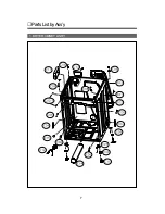
Страница 7: ...6 Ensamblesecadoradegas TAPA SUPERIOR SOPORTETAMBOR FRONTAL PANEL F RONTAL PCB CONTROL ENSAMBLE GABINETE ENSAMBLE TAMBOR CABINETE FRONTAL QUEMADOR DRUM SUPORTE POSTERIOR DUCTO DE AIRE ...

Страница 8: ...1 DRYER CBINET ASS Y PartsListbyAss y 7 ...

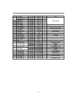
Страница 9: ...xingPlate C07 SUPPORTERLEGF 3615304200 SECC3 0T 2 C08 SUPPORTERLEGR 3615304300 SECC3 0T 2 C09 FIXTURELEG 3612006400 ABS 4 C10 FOOT 3612100700 BUTYL 4 SCREWTAPPING 7122401411 T2STRS4x14 2 ForfixingSupporterLegF R C11 PCBDRYERMAINAS PRPSSWAD40 UL Electricmain 1 Electrictype PRPSSWAD60 UL Gasmain 1 Gastype SCREWTAPPING 7122401411 T2STRS4x14 2 ForfixingMainPCBtoCabinet C12 HARNESSAS 3612797000 UL E Dr...

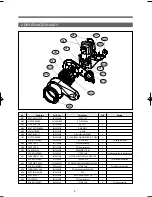
Страница 10: ...FAN F 3611144900 PP Heat resisting 1 M09 CASE FAN R 3611145000 PP Heat resisting 1 M10 GASKET PIPE 3612323200 EPDM 320 15 2 0t 1 SCREW TAPPING 7112401411 T1 TRS 4x14 3 For fixing case fanr to bracket motor M11 THERMOSTAT FAN 3619047900 UL 70ON 85OFF 125V 15A 250V 7 5A 1 SCREW TAPPING 7121300811 T2S PAN 3x8 2 For fixing thermostat fan M12 THERMISTOR FAN 361AAAAC20 UL DRYER R40 26 065K R90 4 4278K 1...

Страница 11: ...ING T1 M4 ø8 1 For fixing G09 G06 G09 IGNITER AS 36189L5800 Ceramic type 120V 60Hz 4A 1 G10 O RING 3614604100 HNBR 1 G11 PIPE AS 3614413800 Pipe Fixture connector 1 WELDING G12 SCREW TAPPING PS W 4 ø12 2 For fixing G01 G11 G13 CAP PIPE 3610918200 PP 1 G14 FIXTURE FUNNEL 3612009200 SGCC 2 0T 1 G15 FUNNEL 3612511300 ALCOST 0 7T 1 G16 SCREW TAPPING T1 M4 8 2 For fixing G14 G15 G17 FLAME SENSOR AS 361...

Страница 12: ...TYPE A03 HEATER AS 3612802500 240V 5 400W 1 ELECTRIC TYPE A04 THERMOSTAT HI LIMIT 3619047600 125 C OFF 94 C ON 250V 25A 1 ELECTRIC TYPE A05 THERMOSTAT CUT OUT 3619047800 140 C OFF 35 C ON 250V 25A 1 ELECTRIC TYPE A06 HARNES HEATER DRYER 3612797100 UL1015 AWG12 1 ELECTRIC TYPE SCREW TAPPING 7122400811 T2S TRS 4x8 MFZN 12 FORFIXINGDUCTINLETF R SCREW TAPPING 7122400811 T2S TRS 4x8 MFZN 4 FOR FIXING S...

Страница 13: ...3610608810 SGCC 1 0t 2 B03 BRACKET SUP R UPPER 3610608910 SGCC 1 0t 1 SCREW TAPPING 7122401411 T2 TRS 4x14 MFZN 7 For fixing bracket supp up side B04 ROLLER AS 3614714400 ASSY 2 B05 WASHER SHAFT 3616039400 T 1 0 ID 10 5 OD 21 2 For fixing roller as B06 NUT HEX 3616039300 M10 P1 5 2 For fixing roller as B07 DUCT INLET AS 3617510110 ALCOSTA 0 6T 1 GAS TYPE 3617510100 ELECTRIC TYPE ...

Страница 14: ...09 BODY FILTER R 3611909700 PP Heat resisting 1 S10 BODY FILTER F 3611909600 PP Heat resisting 1 S11 FILTER AS 3611909810 PP NYLON MESH 1 Insert injection S12 DUCT OUTLET AS 3617510400 DWR WE31 ALCOSTA0 6t 1 SCREW TAPPING 7122401408 T2S TRS 4x14 SUS 3 For fixing Body Filter to Sup Drum F SCREW TAPPING 7122401408 T2S TRS 4x14 SUS 3 For fixing Duct Outlet As to Sup Drum F S13 SENSOR MOISTURE 3614825...

Страница 15: ...t y Remark D01 DRUM 3617010000 SUS 0 5t ø660 x 570 1 D02 LIFTER 361A401000 Heat resisting PP 3 SCREW TAPPING 7122502008 T2 TRS 5x20 SUS 12 For fixing lifter D03 SEAL DRUM AS 3614010600 Pelt Synthetic leather 2 D04 PAD DRUM 3614111110 BUTYL 4 D05 V BELT 3616591200 POLY TYPE 2 340mm 1 ...

Страница 16: ...LASS 3618304300 Transparent ABS 1 D04 HINGE DOOR 3612903600 Zn Dc Zn Plated 1 D05 CAP HINGE DOOR 3610916500 POM 2 D06 FRAME DOOR O 3612208110 ABS 1 D07 GASKET DOOR 3612323000 TPE 1 D08 COVER HANDLE 3611428310 ABS 1 D09 HOOK DOOR 3613101100 POM 1 SCREW TAPPING 7115401608 FLT 4x14 SUS 1 For fixing hook door SCREW TAPPING 7115402008 T1S FLT 4x20 SUS430 NATURAL 15 For fixing the attachment with door o...

Страница 17: ...15 9 PLATE T AS No Part Name Part Code Description Qtt y Remarks T01 PLATE TOP 3614533010 SECD 1 2T 1 T02 PLATE SUPPORTER AS 3615304100 ABS EPDM 2 SCREW TAPPING 7122401411 T2S TRS 4x14 MFZN 4 ...

Страница 18: ...G03 SUPPORTER HINGE 3615304400 SGCC 2 0t 2 G04 DOOR LOCK AS 3613802500 1 SCREW TAPPING 7122401409 T2S TRS 4x14 SUS430 2 For fixing door lock as G05 SWITCH DOOR 3619047700 125V 5A 1 G06 DOOR AS 36117ABQ00 DWD WE31 1 SCREW MACHINE 3616051229 STS430 F L BOLT SE 5x12 1 For fixing hinge cabinet f G07 LABEL WARNING F 3613558800 PVC 1 G08 LABEL CAUTION F 3613557600 PVC 1 G09 LABEL RATING 3613558900 PVC 1...

Страница 19: ...Y 3615504900 Transparent ABS UT 0510 1 F08 BUTTON FUNCTION 3616636100 ABS 1 F09 WINDOW FUNCTION 3615505000 ABS 1 F10 BUTTON OPTION 3616636200 Transparent ABS TR558 1 SCREW TAPPING 7122401411 T2 TRS 4x14 MFZN 7 F11 BUTTON TIME 3616636300 ABS 1 F12 PCB F AS PRPSSWAD50 DWR WE31 1 F13 CUSTOM LED 3613015500 ABS 1 F14 CASE PCB F 3611145310 ABS 5VB VE 0856 1 F15 BUTTON DIAL AS 3616634700 DWD 130RP 1 F16 ...

Страница 20: ...a La puerta de la secadora puede ser instalada para abrir a derecha o a la izquierda Siga las instrucciones para cambiar la dirección en que abre la puerta Nota La puerta y el seguro deben de estar alineados al centro cuando se cierra la puerta ...

Страница 21: ...OL GAS PROPORTIONAL CONTROL 1 Sensor drying courses 7 Manual drying courses 4 1 Humidity sensor 2 Temperature sensor at the duct outlet 1 Motor 2 ELECTRIC HEATING HEATER 2 5KW 2UNIT 3 GAS VALVE ON OFF CONTROL PROPORTIONAL CONTROL 1 Operation display custom LED high brightness LED 18 88 Course and operation display 3mm LED 1 Electric type 2 Gas type on off control or proportional control 1 PANASONI...

Страница 22: ...r sensor está en seco y muy seco 2 Descripción de cursos Normal Cotton Towels HEAVY DUTY BULKY LARGE Very Dry 1 01 1 05 1 05 1 10 More Dry 54 1 02 55 1 00 NIVEL DE Normal 47 59 50 55 Less Dry 40 56 45 50 Damp Dry 33 53 40 45 Nivel por omisión Normal Normal Normal Normal TEMP CONTROL Medium Mid High High High ANTI Time 1 41 1 45 1 45 1 50 BACTERIAL TEMP High High High High SECADO POR SENSOR Perm Pr...

Страница 23: ...B Niveldesecadonoesseleccionado C Eltiemponosemodificainclusosilatemp escambiada D LosLED sdeniveldesecadonopuedenseleccionarseenciclosdesecadoportiempo elniveldetemp esaltoporomisión E El Tiempo puede cambiarse usando los botones More Time y Less Time buttons en los ciclos de secado manuales F Pesionando los botones MAS y MENOS aumenta o disminuye minutos de secado El tiempo maximo es de 1 55 yel...

Страница 24: ...Start Button to automatically select Normal Course Check Filter of Custom LED goes on and off before you press Start Button High of initial Beeper goes on and the previous Beeper value is displayed when you switch on the power B Operation Selection Select operation with Course Switch Button Check Filter of Custom LED goes on and off before you press Start Button Once the unit starts operating Chec...

Страница 25: ...rse Dry Level Temp Control Time Dry Beeper goes on and Custom LED displays Dry Cooling Option LED may go on and off according to your selection C Operation Process Once operation starts LED of Custom LED goes off Humidity data are not produced and Heater is controlled by the temperature set by Temp Control Time is not changed but drying cooling continues during the time set initially 4 Process of ...

Страница 26: ... if Air Dry of Manual Course is selected for Temp Control is not available 2 Operación de válvula de Gas La válvula de gas enciende y apaga cotinuamente de acuerdo a la temp medida por los sensores Sin embargo el termostato de operación puede apagar el quemador al alcanzar una temperatura muy elevada Independientemente de la temperatura que registra la PCB Para valores de temp vea la tabla Temp Co...

Страница 27: ...and off indicator goes on and the machine stops If you press the button again the operation is resumed D If you press Pause Button other buttons or the encoder switch does not function That is you can not change the operation once it starts unless switching off the power 1 Power is immediately switched off after an operation is done 2 Power is switched off after 10 minutes if no button is selected...

Страница 28: ... Selecionando curso por tiempo los LED s de nivel de secado se apagan no pueden selecionarse La temperatura por omisión es ALTA D Los 5 niveles de temperaturas están dsiponibles 6 Beeper A If you press this button the following is displayed in order High Low Off B Then the volume of the beeper changes C You can not change the beeper while the unit is in operation or stops temporarily 7 More Time A...

Страница 29: ...n D OnceRackDryischosen youcannotselectWrinkleCare Anti Bacterial Damp Dry Beep 11 Anti arrugas A Selecionando Anti arrugas nocambianlostiemposprogramados B Para prevenir arrugas el motor continúa funcionando por 10 segundos y para 5 minutos y 50 segundos calentadorseapaga despuéstodalaoperación incluyendoenfriamiento finaliza C Elcursoparasolamentesisepresionapausaoseapagalasecadora D Puede cance...

Страница 30: ...Damp Dry Beep is not available Level More Time Less Time Custom Rack Dry Wrinkle Anti Damp Dry Program Care Bacterial Beep Bulky Large O O O O O Heavy Duty O O O O O Cotton Towls O O O O O Normal O O O O O Perm Press O O O O Delicates O O O O Ultra Delicates O O O O Speed Dry O O O O O Freshen Up O O O O O Air Dry O O O O O Dry O O O O O ...

Страница 31: ... Dry Beep and More buttons are pressed at the same time 4 Then Heater 1 Heater 2 and the motor are turned on 5 Check the temp initially and 2 minutes later Measure the difference If the difference is 20 C or greater OK is indicated If between 5 C 19 C H6 is displayed indicating disconnection of one heater If 5 C or below H4 is displayed indicating disconnection of two heaters 5 H3 Error Detector d...

Страница 32: ...s Compartido secadora eléctricaygas 2 Revisa sensor humedad 0 5 1 xx Compartido secadora eléctrica y gas 3 Revisa sensor Temperatura 0 5 2 xx Compartido secadora eléctrica y gas 4 Revisa SW de puerta 0 5 dc do Compartido secadora eléctrica y gas 5 Revisa Motor 0 5 4 nr Compartido secadora eléctrica y gas 6 Revisa Ignitor 0 5 5 U1 Secadora de gas 7 RevisaVálvula1 0 5 6 U2 Secadora de gas 8 Revisa V...

Страница 33: ...NSOR2 blue HumiditySENSOR none green GND 3 2 2 1 3 2 1 2 1 1 1 2 3 4 5 6 RELAY DEL MOTOR RELAY DEL IGNITOR TRANS FRONT PCB pink MOTOR white I GNITOR purple DOOR CHECK DETECTOR DE FLAMA brown blue VALVULA control black gray blue ENTRADA 120 VCA black orange SENSORES ...

Страница 34: ...perficie es plana Retire objetos Desensamble la unidad y retire objetos Asegure ventilador Reduzca la carga Retire objeto Cambie banda Falla en cable de alimentación Fusible de servicio desconectado Cable de poder dañado Terminal de controlador desconectada Terminal desconectada del block de conexiones Fusible abierto Rango para gas 120V Rating for electric type 120V 240V Falla en la conexión Fall...

Страница 35: ...33 2 DIAGRAMA SECADORA DE GAS ...

Страница 36: ...or right Balance the unit on the floor with the leg adjust as so that the inclination is not greater than 1 inch 2 Outlet Duct Connection Never use a plastic or aluminum foil duct Use a durable 4 inch metal duct the duct outlet is provided with the dryer Ask local shops for an additional duct Make the duct outlet the shortest possible length Clean the duct before installation Do not use a bent duc...

Страница 37: ... screws isdropped intotheheaterwhenassembling Becarefulofthedirection insertionofthe connector Useonlystandardscrews 7 Replacingthesensor Tempandsafetysensor Becarefulofthedirection insertionoftheconnector Useonlystandardscrews 8 Doorassembly Doorhinge Becarefulnottoscratchchromiumplatingwhen fasteningthescrewstofixthedooras Aclaimis expected 9 Disassembly assembly Dooras Becarefulabouttheup downw...

Страница 38: ...n30secondsto ignitegas FlameSensor 3614825700 10RS43828 120V60Hz5 75A Whenheatsourceisdetected contact pointisopenedwithin12 20secondsto turnoffigniterbeforegasignition When heatsourceisextinguished contactpoint isclosedwithin26 40seconds Thermostat 3619047610 60T21 95 C Off 70 C On Topreventoverheatingaroundburner Hi Limit 125V 25A250V 25A duringnormaloperation powerlineof flamesensoriscutoffwhen...

Страница 39: ...on If temperatures are normal the terminals of this part are connected to each other Put the round metal part into boiling water and check if the resistance between the terminals drops to 0 3 or below Put the same part into cold water and check if the terminals are opened If the terminals do not react as mentioned above replace them 4 Procedure of replacement 1 Plate Top remove 2 Panel F Ass y rem...

Страница 40: ...he drum does not rotate check the door switch belt switch and thermostat fan If the lamp is still off remove panel f ass y and check if 120v voltage is applied to the lamp If the lamp is off even though the 120v voltage is being applied replace the lamp Cf If 120v voltage is not applied to the lamp replace the door switch 4 Procedure of replacement 1 Plate Top remove 2 Panel F Ass y remove 3 Cabin...

Страница 41: ...opened Run the dryer by pressing the power and start buttons As the drum begins rotating check if the lamp is turned on after opening the door If the drum does not rotate check the door switch contact Cf Check a belt switch and thermostat fan also for the problem If the lamp is still off while the drum is running remove panel f ass y and check if 120v voltage is applied to the lamp If 120v voltage...

Страница 42: ...is in normal operation if the drum rotates Start the unit and check if the drum operates If the drum fails to rotate press the power button to stop the dryer and then again to check if the motor runs If you can not hear the running of the motor disassemble the dryer and check the belt switch contact Press the lid of the belt switch If the resistance between contacts is greater than 1 replace the b...

Страница 43: ...42 7 Remove wires and 2 screws that fix the switch 8 Assemble the parts in reverse order Belt Switch ...

Страница 44: ...eration You can test the resistance of the thermistor as follows Put the metal rod into cold water 10 20 C 40 within 30 seconds Put the metal rod into boiling water 95 100 C 4 within 30 seconds If H2 error is displayed when you press the power and start button the thermistor is not connected so replace it 4 Procedure of replacement 1 Plate Top remove 2 Panel F Ass y remove 3 Cabinet Front Ass y re...

Страница 45: ... as you start the unit the motor is in normal operation If the drum fails to rotate 1 Remove Plate T and check if the belt is damaged 2 Check if the door switch is in normal operation 3 Remove the drum and check the thermostat fan 4 Check the belt switch 5 Run the unit while you press the lid of the belt switch and see if the motor starts operating If a fault is found in any part mentioned above r...

Страница 46: ...s and the motor ass y 7 Remove the cover fan and 3 screws 9 Remove wires and 2 clamps that fix the motor bearing to detach the motor 0 Assemble the parts in reverse order Loosen the 3 screws as indicated with a circle Loosen the 3 screws as indicated with a circle ...

Страница 47: ...ature resistance between two terminals of this part is generally between 300 400Ω Part is defective if resistance between terminals measured after separating cable connected to igniter is 250Ω or less Part is defective if cracks are found when separating igniter and closely observing the surface In two of the above conditions igniter is defective therefore needs to be replaced 4 Procedure of repla...

Страница 48: ...his part Part is defective if resistance between terminals measured after separating cables connected to sensor flame is 1Ω or more Part is defective if the area between terminals is not opened 30 seconds after separating sensor flame and holding flame of lighter near transparent window at the bottom less than 1cm Flame of lighter must be as long as the length of transparent window and the flame m...

Страница 49: ... mal function After operating air dry program for 5 minutes or longer the terminal status of this part must be short Part is defective and to be replaced if resistance between terminals measured after separating cables connected to sensor flame is 1Ω or more 4 Procedure of replacement 1 Remove plate top 2 Remove panel F ass y 3 Remove cabinet front ass y 4 Remove frame upper 5 Remove drum ass y 6 ...

Страница 50: ...top two or three times to restore If resistance between terminals is 1ߟ or more after manual restoration replace part as it is defective This part is restored to be reused if placed at temperature of 35 C or lower However this is an extremely low temperature that cannot be reached with general refrigerator for household use Therefore it is effective to press knob for restoration 4 Procedure of re...

Страница 51: ...tance between two terminals of each valve is 2 4 2 7 kΩ Part is defective if resistance between terminal measured after separating cables connected to valve gas AS is 2 0Ω or less or 3 0 kΩ or more 4 Procedure of replacement 1 Remove plate top 2 Remove panel F ass y 3 Remove cabinet front ass y 4 Remove frame upper 5 Remove drum ass y 6 Remove 2 screws fixing pipe AS in position 7 Remove 4 screws ...

Страница 52: ...ornillo 2 Separe el panel frontal cuide no dañar los ganchos internos 3 Separe la tapa empujando al frente en dirección de la flecha 1 Retire 3 tornillos del frente 2 Retire 4 tornillos traseros MÉTODO DE DESENSAMBLE Empuje con cuidado hacia arriba presionando hacia dentro ...

Страница 53: ...52 GABINETE FRONTAL 1 Retire 4 tornillos superiores 2 Saque el filtro 3 Retire 3 tornillos 4 Levante el gabinete en dirección de la flecha jalando hacia el frente 5 Desconecte el switch de la puerta ...

Страница 54: ...ÁMPARA PCB Y SENSOR 1 Separe conector de lámpara 2 Separe conectores de PCB 3 Separe conector sensor de humedad 1 Retire 1 tornillo de cada lado del marco 2 Retire los tornillos superiores 3 Separe el marco después de quitar el arnés ...

Страница 55: ...CB MAIN DUCTO DE SALIDA 1 Retire 2 tornillos de cada lado 2 Retire 1 tornillo de abajo 3 Retire el ducto en dirección de las flechas 1 Retire 2 tornillos 3 Jale hacia arriba libere los ganchos de la PCB 1 2 ...

Страница 56: ...55 TAPA POSTERIOR 1 Retire 10 tornillos SOPORTE DEL TAMBOR TRASERO 2 1 1 Retire terminales del calefactor sólo secadora eléctrica 2 Retire 7 tornillos 3 Retire soporte en dirección de la flecha ...

Страница 57: ...ABLEADO Y MOTOR 1 Separación del sensor de temperatura Desconecte Retire el tornillo 2 Separación del termostato Desconecte Retire 2 tornillos 3 Desconecte micro switch del motor 4 Retire conector del motor ...

Страница 58: ...57 BLOCK DE TERMINALES 1 Remove cover terminal 2 Remove 3 screws sólo secadora eléctrica ...

Страница 59: ...58 ENSAMBLE MOTOR 1 Retire 6 tronillos y separe el motor 2 Desensamble ventilador Remueva 2 tornillos 3 Retire la tuerca cuerda izq y separe el ventilador del motor ...

Страница 60: ...4 Desensamble caja ventilador Retire 3 tornillos 5 Desensamble base del motor Retire 2 abrazaderas 1 cada extremo LÁMPARA 1 Retire 1 tornillo 59 ...

Страница 61: ...60 CAJA FILTRO Y SENSOR DE HUMEDAD 1 Caja filtro Retire 2 tornillos 2 Desconecte Sensor Humedad 3 Remueva Sensor ...

Страница 62: ...61 3 Seguro de puerta Retire 2 tornillos y quite el seguro de puerta 1 Separación de bisagra y soporte tambor frontal Retire 2 tornillos 2 Retire 13 tornillos PUERTA ...

Страница 63: ...4 Switch de Puerta Presione los seguros y empuje hacia el frente ...

Отзывы: