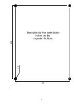
4
2.2.3. Power supply connection
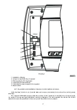
Connect the power supply cable to the terminal marked “POWER” observing the following layout:
−
„+” – power supply wire “+24V”;
−
„-“ – power supply wire “-24V”;
−
“
Ω
”
– earthing wire.
The cable cross section should not be less than 0,75mm
2
for the power supply wires and earthed.
Connect the other end of the power supply cable to the mains of the interactive fire control panel
IFS7002 or to the power supply device as the voltage polarity should be observed.
3. Safety instructions
The personnel installing and repairing the repeater should be aware of the construction and
performance of the equipment and the general safety measures.
It is not permitted connecting to not earthed or indirectly earthed power supply mains.
Any faults should be repaired after the power supply cable is disconnected from the mains.
The repeater could be installed in a premise with normal fire danger according to the fire construction-
technical norms.
4. Starting the repeater
Check the correct connection to the power supply mains.
Check the correct connection of the peripheral devices.
Attention! The repeater operates with constant voltage (10-30)V DC.
When CAN network is made it is possible 32 remote objects (fire control panels and repeaters) to be
connected as there is Master and all other objects are subordinate. The master repeater addresses all
other devices and depending on the situation receives or transmits data to the remote objects.
The master repeater is programmed from SET-UP Menu as “MASTER”. The data for all other objects
is also programmed in it: - Address;
- Text messages for the objects;
- Communication speed.
To the subordinate (SLAVE) devices it is programmed: - Address;
- Text message;
- Communication speed.
The data programmed in the master repeater and the remote devices should be accurate in order the
communication to be executed.
It is recommended after all devices are switched on the status of each one of the remote objects to be
checked from menu LISTS/FAULTS/LAN Objects. Status “YES” shows that there is communication with
that address; and status “NO” - no communication with the respective object.
If the communication with a certain object is interrupted due to any reason, the repeater will indicate
an error and will provide information about the device without a connection.
UniPOS wishes you pleasant work!

