


11
THREADING
Draw looper and needle threads into the machine and start
operating on a piece of fabric. Refer to threading diagram
(Fig. 1) for manner of threading this machine.
LOOPER THREAD CAST-OFF WIRE
Looper thread cast-off wire (A, Fig. 13) located on the take-
up shield (B) controls the amount of slack thread in the system
and can be moved to any position. It should be set laterally
so that it is midway between the two discs of take-up (C) and
the tip parallel with the discs.
It is usually set toward the take-up to almost the limit of its slot
so that it barely clears the highest point of the take-up. The
height and lateral adjustment of the retainer affects the
control of looper thread as looper moves to the left. Ordi-
narily it will be set in approximately a horizontal position.
More looper thread is given to the stitch when the retainer is
raised and set towards the take-up. However, if the retainer
is raised too high, the looper thread triangle may be wiped
under the blade of the looper, causing traingle skips or pulled
down stitches. This can be checked by observing the action
of the looper thread as the looper moves to the left.
THREAD TENSIONS
Tension on the needle thread should be only sufficient to produce uniform
stitches on the under surface of the fabric. Tension on the looper thread
should be just sufficient to steady the thread.
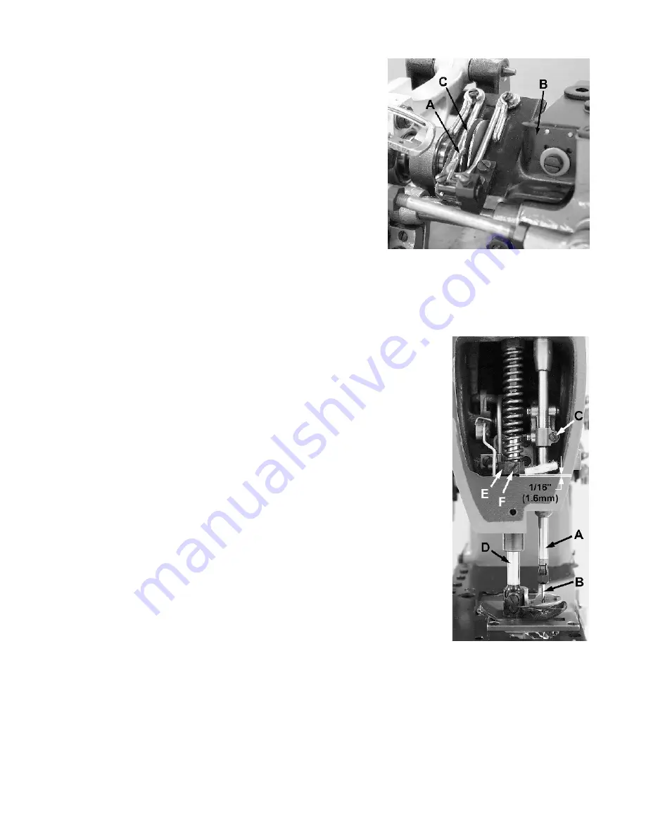
PRESSER BAR HEIGHT
Height of presser bar (D, Fig. 14) is set correctly if it is possible to remove
the presser foot when the foot lifter lever, located at the back of the
machine and extending above the upper crank chamber cover is fully
actuated (pulled to the right). There should be approximately 1/16 inch
(1.6mm) clearance between lower surface of the presser bar connection
and guide (E) and bottom surface of head opening in the bed when foot
lifter lever is released and presser foot lying flat on the throat plate with
feed dog below throat plate.
Adjustment can be made by turning handwheel to position needle bar at
bottom of stroke. Loosen screw (F) and while holding presser foot down
on throat plate, position presser bar connection and guide as required to
attain specified clearance and retighten screw.
PRESSER FOOT PRESSURE
Regulate the presser spring regulating screw (A, Fig. 14) so that it exerts
only enough pressure on the presser foot to feed the work uniformly when
a slight tension is placed on the fabric. Turning it clockwise increases the
pressure, counterclockwise acts the reverse.
Fig 13
Fig 14
Fig 14