10
SETTING THE LOOPER GAUGE (CONT.)
Move the needle guard to the side so the needle will not strike it. Turn the handwheel in operating direction
until the looper holder frame has travelled fully to the rear. At this time the distance between the centerline
of the needles and the points of the loopers should be 1/8" (3.2mm) . If adjustment is necessary loosen
hexagon head clamp screw (D, Fig. 6 Inset) at the right end of looper holder driving arm (E) and move forward
or backward as required. Tighten screw (D) and recheck settings.
SETTING THE NEEDLE GUARDS
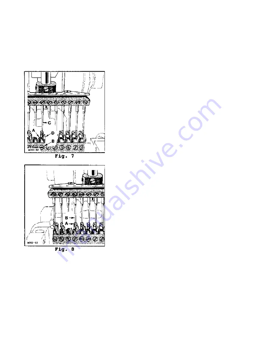
The needle guard screws (A, Fig. 7) cannot be accessed
once the loopers are tightened so the needle guards must
be set first. Loosen looper screw (B) and swing the looper
to the side so the needle will not strike it. Do not remove
the looper because the needle guard looper hole must
remain aligned with the hole in the looper holder. Turn the
handwheel in operating direction until needles (C) are at
their lowest point of travel. Position needle guard (D) so it
touches but does not def lect the rear of needle (C). Tighten
needle guard screw (A).
SETTING THE LOOPERS
Turn the handwheel in operating direction. When each
looper (A, Fig. 8) moves forward the point should pass the
left side of needle (B) with a clearance of 0.000" to 0.003"
(O.OOMM to 0.08MM).
SETTING THE RETAINERS
The retainers must be adjusted as close as possible to the
top of the loopers without touching them and also set from
the right to left for proper stitch formation.
Insert retainers (A, Fig. 9) into retainer holder bar (B) with
the notched ends 1/32" (0.8mm) from the needles and the
side of the notches facing the needles and tighten screws
(C).
Loosen screws (D) in the retainer holder bar connection bar (E) and rock bar (B) so the underside of the
retainer is as close as possible to the top of the looper without contacting it. Position the needle bar as
high as possible and pull looper throw-out plunger knob (F) to the left, releasing the looper holder. Make
sure the loopers do not hit the underneath side of the retainers.
Содержание 54200J-12-16
Страница 1: ...ADJUSTING INSTRUCTIONS MANUAL NO INS9203 STYLES 54200J 12 16 54200 SERIES REV 10 22 98 ...
Страница 16: ......


