


3: Installation
3-14
UPS469-01-00 PowerWAVE 3000T User Manual Dated 05-04-13
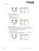
Single Input Feed
1.
Refer to the appropriate illustration in Figure 3.5 to Figure 3.8 and connect the UPS input supply cables
to terminals 1L1 and 1N [
1L1, 1L2, 1L3 and 1N in a 3-phase fed unit
] on the UPS mains supply terminal
block. Ensure correct (clockwise) phase rotation in the case of a 3-phase unit.
2.
Secure the cables to the fixing rail mounted below the terminal blocks.
Dual Input Feed
1.
Refer to the appropriate illustration in Figure 3.5 to Figure 3.8.
2.
Remove the links between 1L1-2L1 on the main terminal block.
3.
Connect the UPS input supply cables to terminals 1L1 and 1N [
1L1, 1L2, 1L3 and 1N in a 3-phase fed
unit
] on the UPS mains supply terminal block. Ensure correct (clockwise) phase rotation in the case of a
3-phase unit.
4.
Connect the UPS bypass supply cables to terminals 2L1 and 2N on the UPS bypass supply terminal
block.
5.
Connect the earth cable from the bypass mains LV-Distribution Board to the protective earth (PE)
terminal on the UPS bypass supply terminal block.
6.
Secure the cables to the fixing rail mounted below the terminal blocks.
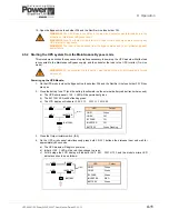
3.4.4 Connecting the UPS output cables
1.
Refer to the appropriate illustration in Figure 3.5 to Figure 3.8. Connect the earth cable from the Output
Load Distribution Board to the protective earth (PE) terminal on the UPS output supply terminal block.
2.
Connect the UPS output cables to terminals 3L1, and 3N on the UPS output terminal block.
3.
Secure the cables to the fixing rail mounted below the UPS terminal blocks.
3.4.5 Final
checks
1.
On completion of the above cabling check that the earthing is complete and conforms to prescribed IEC
standards or local regulations.
2.
Ensure that all cables are securely fastened to the fixing rail mounted below the UPS terminal blocks.
3.
Screw the terminal cover plate back on the UPS, making sure that the earthing wire is correctly attached
on the terminal cover plate.
4.
Move the UPS to its final position and lock it by applying the brake on the castors (cabinet A) or adjusting
the locking feet (cabinet B/C).
CAUTION: The input neutral cable to terminal 1N must be permanently connected and not
switched by the input supply circuit breaker.
CAUTION: The input neutral cable to terminal 1N must be permanently connected and not
switched by the input supply circuit breaker.
CAUTION: The bypass neutral cable to terminal 2N must be permanently connected and not
switched through the bypass supply circuit breaker.
CAUTION: The output neutral cable to terminal 3N must be permanently connected and not
switched by the output (load) supply circuit breaker.
Содержание PowerWave 3000T
Страница 1: ...Pioneering solutions for total power protection PowerWave PW 3000 T User Manual ...
Страница 2: ......
Страница 8: ...1 Safety 1 2 UPS469 01 00 PowerWAVE 3000T User Manual Dated 05 04 13 ...
Страница 30: ...3 Installation 3 18 UPS469 01 00 PowerWAVE 3000T User Manual Dated 05 04 13 ...
Страница 44: ...4 Operation 4 14 UPS469 01 00 PowerWAVE 3000T User Manual Dated 05 04 13 ...
Страница 56: ...7 Options 7 8 UPS469 01 00 PowerWAVE 3000T User Manual Dated 05 04 13 ...


