background image

INSTALLATION & OPERATION

Installation of gas shielded arc welding
(1)

 Turn the power source on and select the MIG function through the STICK/MIG  

selector. (See Panel Structure Diagram Number 7)

(2)

 Plug the welding torch into the output socket “10” on the front panel, (See Panel 

Structure Diagram Number 10) and tighten it.

(3)

 Insert the earth cable plug into the negative socket “8” on the Panel Structure  

Diagram, and tighten it clockwise.

(4)

 Insert the fast plug on the wire feeder into the output socket “GAS” on the  

clapboard, and tighten it clockwise. (See Clapboard Structure Diagram Number 15)

(5)

 Remove the right side cover of the unit and push the wire spool onto the spindle. 

Make free the end of the wire and cut it smoothly. Unlock the pressure arm and align the 
wire into the groove of the drive roll putting a short part of the wire into the torch recep-
tacle. Check that the drive roll and contact tip in MIG torch being used complies with the 
wire diameter, replace if necessary. Lock the pressure arm and check that the bearing 
roll presses the wire exactly into the groove.

(6)

 Press selector switch on for “wire inching”  (See Panel Structure Diagram Number 3)

Press and hold until wire is visible at end of torch. 

(7)

 Tightly connect the gas hose, which comes from the back of the machine to the 

brass nipple of supplied  regulator, adjust argon regulator to deliver the required litres 
per minute. 
NOTE. reffer to instruction manual of argon regulator for proper use.

(8)

 Adjust the welding voltage adjustment knob and wire feeding speed adjustment 

knob according to practical needs to get the desired welding voltage and welding 
current. (See Panel Structure Diagram Number 5&6)

(9)

 Press the welding torch switch, and welding can be carried out.

(10)

 Adjust the burnback time potentiometer on the clapboard to get the desired length 

of welding wire stretching into the contact tip after welding.
(See Clapboard Structure Diagram Number 14)

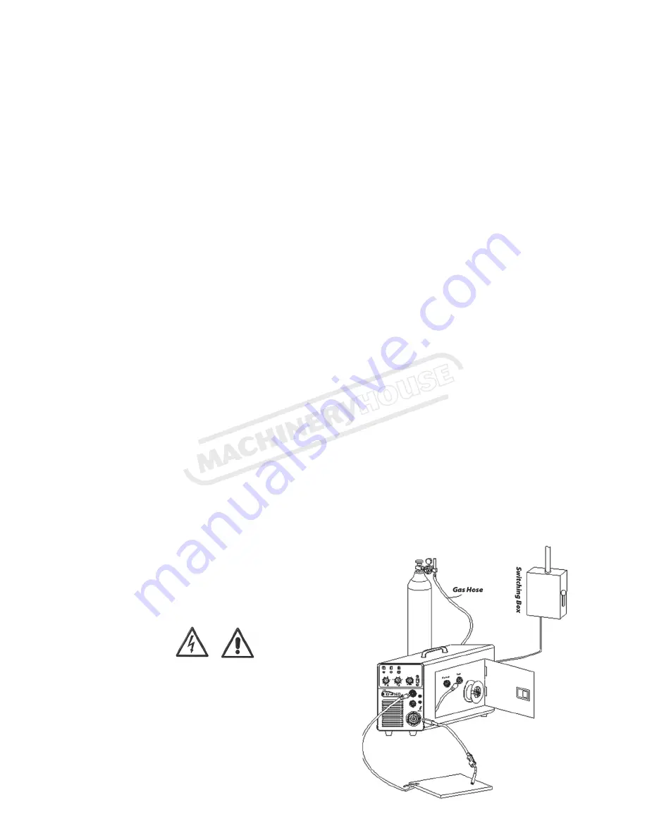
Installation sketch map

WARNING!

Disconnect the Electrode Holder cable  
from the machine before using MIG 
function. If cable is not disconnected  
welding voltage is present and can cause  
arcing or 

fl

ash.


Page 9

Instruction Manual for MIG-TIG-MMA 250 (W179)

15/12/2014

Содержание KUMJR165

Страница 1: ...INSTRUCTION MANUAL MIG TIG MMA 250 INVERTER Multi Function Welder 240V 30 250A W179 Page 1 Instruction Manual for MIG TIG MMA 250 W179 15 12 2014 ...

Страница 2: ...guarantee for this welding Power Source from the date of purchase Refer to Unimig for further details Please read and understand this instruction manual carefully before the installation and operation of this equipment The contents of this manual may be revised without prior notice and without obligation This instruction manual is issued on 1st April 2008 UNIMIG pursue a policy of continuous resea...

Страница 3: ...cluding welding gloves whilst the welding operation is performed Measures should be taken to protect people in or near the surrounding working area from all hazards associated with welding Fire hazard The welding sparks may cause fire therfore remove flammable material away from the working area Have a fire extinguisher nearby and have a trained person ready to use it Noise possibly harmful to peo...

Страница 4: ...ear drive wire feeder for 5Kg 15kg spool Euro style MIG torch connection IP21S rating for environmental safety protection Stepless voltage and wire feed control Scratch start DC TIG welding Excellent arc stability for MIG MMA TIG welding Light weight and portable Wire inch and burn back functions MACHINE FEATURES Page 4 Instruction Manual for MIG TIG MMA 250 W179 15 12 2014 ...

Страница 5: ...CIRCUIT DIAGRAM Page 5 Instruction Manual for MIG TIG MMA 250 W179 15 12 2014 ...

Страница 6: ...35 160A 100 95A 35 175A 100 103A MMA welding 35 140A 100 83A 35 160A 100 95A WELDING VOLTAGE RANGE DC 15 5 22 Volts 15 5 23 Volts WIRE SIZE mm 0 6 0 8mm Ferrous 0 6 0 9mm Ferrous 0 9 1 0mm Aluminium 0 9 1 0mm Aluminium 0 6 0 8mm Stainless Steel 0 6 0 9mm Stainless Steel 0 9 1 2mm Flux cored 0 9 1 2mm Flux cored DIMENSIONS mm 480 230 360mm 480 230 360mm WEIGHT Kgs 17 Kgs 19 Kgs MAIN PARAMETER 165 1...

Страница 7: ... 220A 100 139A 35 250A 100 148A MMA WELDING 40 200A 100 125A 35 224A 100 137A WELDING VOLTAGE RANGE DC 15 5 25 Volts 15 5 26 5 Volts WIRE SIZE mm 0 6 1 2mm Ferrous 0 6 1 2mm Ferrous 0 9 1 2mm Aluminium 0 9 1 2mm Aluminium 0 8 1 0mm Stainless Steel 0 8 1 0mm Stainless Steel 0 9 1 2mm Flux cored 0 9 1 2mm Flux cored DIMENSIONS mm 580 230 450mm 580 230 450mm WEIGHT Kgs 23 Kgs 24 Kgs MAIN PARAMETER 22...

Страница 8: ...ucture Diagram Number 4 Generally the required welding current is listed as follows Ф2 5mm 70 100A Ф3 2mm 110 160A Ф4 0mm 170 220A 3 Connection of Output Cables Two sockets are available on this welding machine For MMA welding the electrode holder should generally be connected to the positive socket while the work piece should be connected to the negative socket However the polarity can be reverse...

Страница 9: ...re arm and check that the bearing roll presses the wire exactly into the groove 6 Press selector switch on for wire inching See Panel Structure Diagram Number 3 Press and hold until wire is visible at end of torch 7 Tightly connect the gas hose which comes from the back of the machine to the brass nipple of supplied regulator adjust argon regulator to deliver the required litres per minute NOTE re...

Страница 10: ...ing used complies with the wire diameter replace if necessary Lock the pressure arm and check that the bearing roll presses the wire exactly into the groove 5a Please note that a knurled drive roller sholud be fitted when using self shielded wire 6 Press selector switch on for wire inching See Panel Structure Diagram Number 3 Press and hold until wire is visible at end of torch 7 Adjust the weldin...

Страница 11: ...the normal performance and service life of this equipment 2 2 Thermal Overload protection Should the machine be used to an excessive level or in high temperature environment poorly ventilated area or if the fan malfunctions the Thermal Over load Switch will be activated and the machine will cease to operate Under this circumstance leave the machine switched on to keep the built in fan working to b...

Страница 12: ...ied attempt to take apart the machine or open the factory made sealing of the machine without the consent of an authorized representative of the manufacturer 10 TROUBLESHOOTING Caution Only qualified technicians are authorized to undertake the repair of this welding equipment For your safety and to avoid Electrical Shock please observe all safety notes and precautions detailed in this manual UNIMI...

Страница 13: ...Y OPTION MIG 165 190 PART NO UMJRTROLLEY2 TIG TORCH OPTION PART NO 17V 4MCP25 TROLLEY OPTION MIG 220 250 PART NO UMJRTROLLEY TIG TORCH OPTION PART NO 26V 4MCP50 Page 13 Instruction Manual for MIG TIG MMA 250 W179 15 12 2014 ...

Страница 14: ...XW WHUPLQDO µ µ RXWSXW WHUPLQDO µ DVW 3OXJ 51 1 HIRUH 00 HOGLQJ LVFRQQHFW WKH IDVW SOXJ RQ WKH ZLUH IHHGHU IURP WKH RXWSXW VRFNHW V 6µ 12 6µ RQ WKH FODSERDUG I FDEOH LV QRW GLVFRQQHFWHG ZHOGLQJ YROWDJH LV SUHVHQW FDQ FDXVH DUFLQJ RU Á DVK 17 Page 14 Instruction Manual for MIG TIG MMA 250 W179 15 12 2014 ...

Страница 15: ...tton 4 Current adjustment knob in MMA welding 5 Voltage adjustment knob MIG MAG 6 Wire Feed adjustment knob MIG MAG 7 STICK MIG selector switch 8 output terminal 1 9 output terminal 1 10 Euro welding torch connector MIG MAG Page 15 Instruction Manual for MIG TIG MMA 250 W179 15 12 2014 ...

Страница 16: ...n must be repaired by an authorised repair agent as appointed by this company Warranty does not cover abuse mis use accident theft general wear and tear New product will not be supplied until Welding Guns of Australia Pty Ltd has inspected product returned for warranty and agree s to replace product Product will only be replaced if repair is impossible If in doubt please ring Page 16 Instruction M...

Отзывы: