


page 6
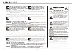
Important Precautions Introduction
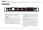
Front Panel Rear Panel
Operating Modes Protection Specifications
Set Up
BANANA PLUG: (Figure 5)
When connecting your speakers to the amplifier using banana plug, be sure that the red and black caps on
the binding post are completely screwed in. Insert the banana plug into the caps of the binding post, be sure
that the banana plug is inserted securely to avoid the risk of popping out.
BARE WIRE CONNECTION: (Figure 6)
When connecting your speakers to the amplifier using bare wire, unscrew the red and black caps on the
binding post, be sure not to completely remove or unscrew the red and black caps. Strip back the wire
insulation ½” (13mm). Insert the bare wire into the hole that was revealed by unscrewing the binding post
cap. After inserting the wire into the binding post hole, screw the binding post cap down on the wire. To
reduce the risk of shock or damage to your amplifier, be sure that the wire connected to one binding post
does not come in contact with that of another.
SPADE CONNECTOR: (Figure 7)
When connecting your speakers to the amplifier using spade connector, unscrew the red and black caps on
the binding post, be sure not to completely remove or unscrew the red and black caps. Insert the spade
connector into the binding post and tighten the caps down on the spade connector. To reduce the risk of
shock or damage to your amplifier, be sure that the wire connected to one binding post does not come in
contact with that of another.
MONO BRIDGE CONNECTIONS: (Figure 8)
Mono bridge operation connections will follow the above descriptions, however, when operating in mono
bridge operation the speaker connections will run between the two positive (red) leads. Use channel two (or
channel four) positive output terminal for the speaker's negative connection and the channel one (or channel
three) positive output terminal for the speaker's positive connection.
Typical speaker output using bare wire.
Insert bare wire into the binding post and tighten.
Typical speaker output using spade connectors.
Insert bare wire into the binding post and tighten.
Figure
7
1/5"
13mm
Figure
6
Figure
5
Figure
8
CH 1
CH 3
CH 2
CH 4
BRIDGE
+
_
BRIDGE
+
_
_
_
+
+
4 Ohms
Minimum
Stereo
Mode
8 Ohms
Minimum
Bridge
Mode
UNiKA
MT-600Q
Содержание MT Series
Страница 12: ...P R O F E S S I O N A L A U D I O ...


