


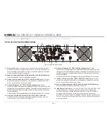


DCA-1300 & DCA-2000 REAR PANEL
11. Fan Outlet Ports -
Cooling air enters the amplifier through the front
grills and exhausts through the fans. Be sure not to block these ports
when installing the amplifier or other associated equipment. Air must
flow unimpeded through these ports.
12. Channel 2 Subwoofer Mode On/Off Switch (DCA-1300 & DCA-2000 only) -
Turns the subwoofer mode for channel two on and off.
13. Channel 2 Frequency Adj. (DCA-1300 & DCA-2000 only) -
This pot
adjust the frequency level sent to your speaker on channel two when
using your amplifier in subwoofer mode.
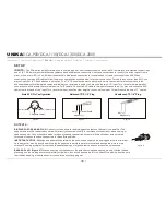
14. Channel 2 Balanced 1/4" TRS & XLR Input Connectors -
These
connectors accept input signals on balanced TRS and XLR input plugs. See
the figures 6-8 for information on polarity. Connectors for each channel are in
parallel; the unused connectors may be used for "loop through" connection
to other amplifiers.
XLR pin setting: Pin-3/signal Negative, Pin-2/signal Positive, Pin-1/Ground.
15. Low Cut Filter Mode Switches (DCA-1100 & DCA-1300 only) -
These DIP switches are used to activate and adjust the built-in Low
Cut Filter, see ”Low Cut Filter” on Page 15.
16. Channel 1 Balanced 1/4" TRS & XLR Input Connectors -
These
connectors accept input signals on balanced TRS and XLR input plugs. See
the figures 6-8 for information on polarity. Connectors for each channel are in
parallel; the unused connectors may be used for "loop through" connection
to other amplifiers.
XLR pin setting: Pin-3/signal Negative, Pin-2/signal Positive, Pin-1/Ground.
17. Channel 1 Frequency Adj. (DCA-1300 & DCA-2000 only) -
This pot
adjust the frequency level sent to your speaker on channel one when
using your amplifier in subwoofer mode.
18. Channel 1 Subwoofer Mode On/Off Switch (DCA-1300 & DCA-2000 only) -
Turns the subwoofer mode for channel one on and off.
19. Mode Selection Switch –
For the DCA-900, DCA-1100 and DCA-1300
all designed with a recessed, two-position switch configures the
amplifier for Stereo or Bridged Mode operation; for the DCA-2000 is
designed with a recessed, three-position switch configures the
amplifier for Stereo, Parallel or Bridged Mode operation. Amplifiers are
factory-configured for Stereo Mode. See section on Mode Selection for
more information.
page 5
Figure
4: DCA-1300 REAR PANEL
UNiKA
DCA-900/DCA-1100/DCA-1300/DCA-2000
CAUTION
MINIMUM LOAD IMPEDANCE
2 OHM PER CHANNEL
4 OHM BRIDGE
AC IN
-120V 60Hz
FREQUENCY
CH-2
CH-1
SUB
WOOF
DIP
ON
1 2 3 4
20Hz
200Hz
SUB
WOOF
FREQUENCY
200Hz
20Hz
NORMAL
NORMAL
CH-1
CH-2
11
14
17
16
19
21
20
11
15
13
22
25
26
27
28
12
18
Introduction Front Panel
Set Up Operating Modes Protection Features Specifications
Rear Panel
Содержание DCA-900
Страница 18: ...Professional Power Amplifiers UNiKA...


