C.I.B. UNIGAS - M039121CE
23
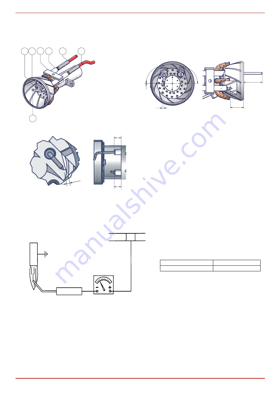
Correct electrodes positioning
To guarantee a proper ignition, the measures indicated in must be respected.
Ensure the locking screw
VE
of the electrodes group is tight before refit the burner.
Fig. 15
Checking the detection current
If the burner locks, execute the following inpesctions. To measure the detection signals refer to the diagrams below. If the signal is less
than the value shown, check the position of the detection electrode, the electrical contacts and if necessary replace the detection
electrode.
Seasonal stop
To stop the burner in the seasonal stop, proceed as follows:
1
turn the burner’s main switch to 0 (Off position)
2
disconnect the power mains
3
close the fuel cock of the supply line
Burner disposal
In case of disposal, follow the instructions according to the laws in force in your country about the “Disposal of materials”.
z
Standard burners (mm)
z
Low NOx burners (mm)
Fig. 16
3
5
4
2
3
1
6
1
detection electrode
2
grounded electrode
3
ignition electrode
4
electrode fixing
5
ignition cable
6
detection cable
90
°
0
3
90°
28
20
2.5
10
10
Connector
µA DC SCALE
2
Detection electrode
Flame
Control box
Minimum detection signal
Siemens LME11
3 µA
Содержание LG35
Страница 27: ...C I B UNIGAS M039121CE 27 Cod 01 319 Rev 5 Single stage burners ...
Страница 28: ......
Страница 29: ......
Страница 31: ...C I B UNIGAS M039121CE 31 ...
Страница 37: ......
Страница 38: ......
Страница 39: ......


