PART II: INSTALLATION
19
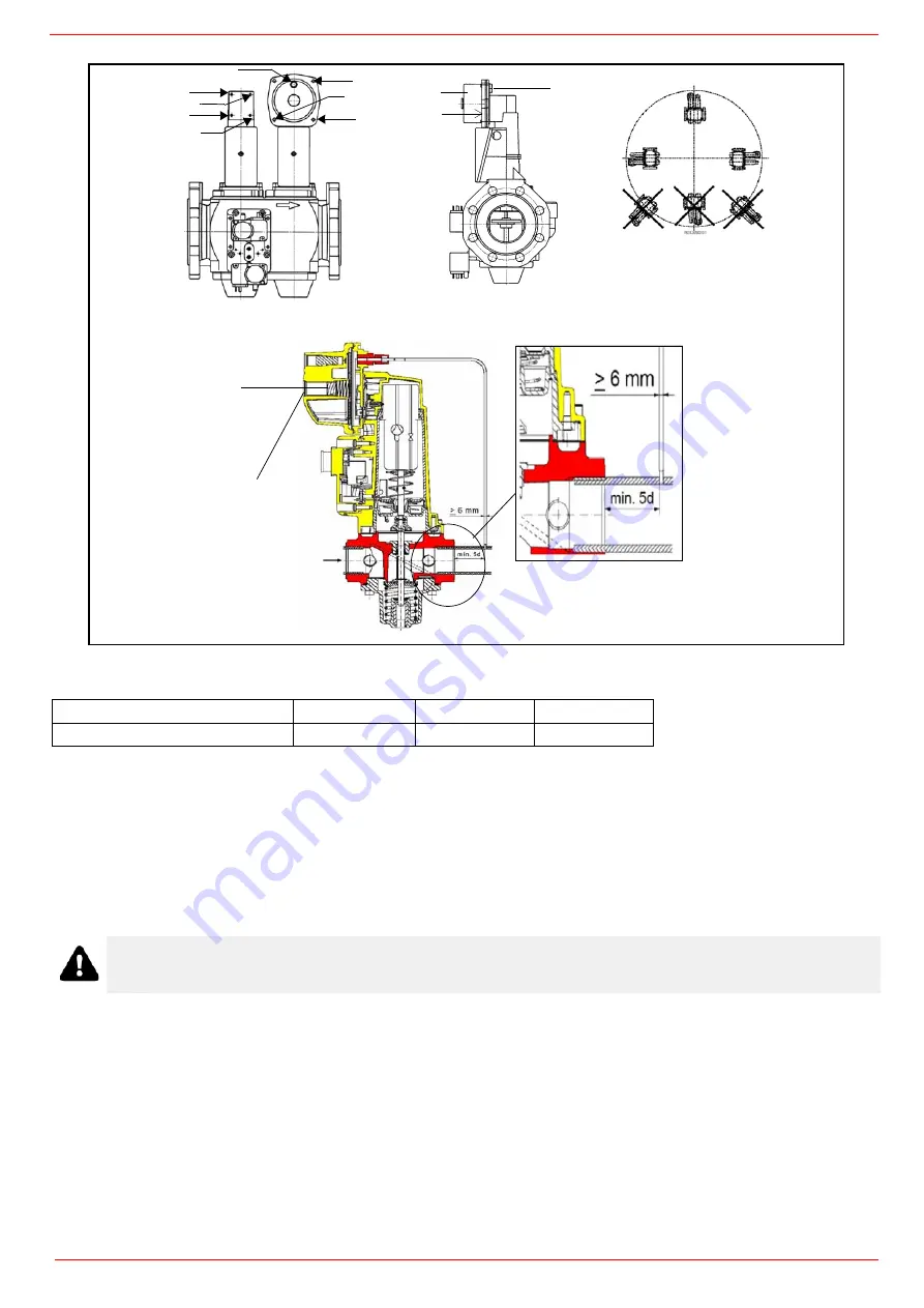
Siemens VGD valves with SKP actuator:
The pressure adjusting range, upstream the gas valves group, changes according to the spring provided with the valve group.
Once the gas train in installed, execute the electrical connections for all its items (gas valves group, gas proving system, pressure
switches).
Gas Filter (if provided)
The gas filters remove the dust particles that are present in the gas, and prevent the elements at risk (e.g.: burner valves, counters and
regulators) from becoming rapidly blocked. The filter is normally installed upstream from all the control and on-off devices.
Integrated proving system (burners equipped with LME7x, LMV, LDU, BT3x)
This paragraph describes the integrated proving system operation sequence:
At the beginning both the valves (EV1 and EV2) must be closed.
Test space evacuating: EV1 valve (burner side) opens and keep this position for a preset time (td4), in order the bring the test
space to ambient pressure.Test atmospheric pressure: EV1 closes and keep this position for a preset time (test time td1). The
pressure switch PGCP has not to detect a rise of pressure.
Test space filling: EV2 opens and keep this position for a preset time (td3), in order to fill the test space.
Test gas pressure: EV2 closes and keep this position for a preset time (td2). The pressure switch PGCP has not to detect a pres-
sure drop down.
If all of the test phases are passed the proving system test is successful, if not a burner lockout happens.
On LMV5x and LMV2x/3x and LME73 (except LME73.831BC), the valve proving can be parameterized to take place on startup, shut-
down, or both.
Performance range (mbar)
0 - 22
15 - 120
100 - 250
Spring colour
neutral
yellow
red
ATTENTION: it is reccomended to install the filter with gas flow parallel to the floor in order to prevent dust fall on
the safety valve during maintenance operation.
BS
BS
SKP1.
SKP2.
BS
BS
SA
SA
TP
D
SIEMENS VGD..MOUNTING
POSITIONS
2
(cap)
1
(spring)
Fig. 9
Содержание HTP2000
Страница 13: ...PART I SPECIFICATIONS 13 Gas pressure in combustion head kW...
Страница 35: ...PART III OPERATION 35 Pump flow rate Nozzle flow rate...
Страница 45: ...PART IV MAINTENANCE 45...
Страница 46: ...PART IV MAINTENANCE 46...
Страница 47: ...PART IV MAINTENANCE 47...
Страница 49: ...Siemens LMV5x Service Manual M12920CC rev 2 1 08 2017...
Страница 56: ...8...
Страница 57: ...9 1 4 1 Servomotor wiring example 1 4 2 Bus cable wiring on LMV5x and AZL doors 1 4 3 EARTH connection example...
Страница 60: ...12 2 2 LMV5x program structure...
Страница 87: ...39...
Страница 94: ......
Страница 95: ......
Страница 96: ...Note Specifications and data subject to change Errors and omissions excepted...
Страница 98: ...Annex1 Example for motor cable...
Страница 99: ......
Страница 100: ...Annex 2 Example for sensor cable...
Страница 101: ......
Страница 102: ......
Страница 106: ......


