


Installation
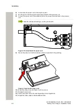
Electrical Installation
3)
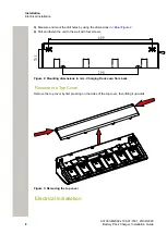
Measure and mark the drill holes by using the dimensions in
.
4)
Drill and fasten the unit to the wall with four screws.
400
290
70
.5
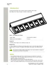
Figure 2: Mounting dimensions in mm - Charging Rack seen from back
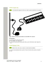
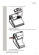
Remove the Top Cover
Remove the top cover by first pressing on the sides of the top cover, then lifting it upwards.
Figure 3: Removing the top cover
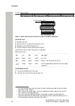
Electrical Installation
A31003-M2000-J106-01-7631, 25/06/2020
8
Battery Pack Charger, Installation Guide