


Manual – 3000 NRL Family
Unidata Manual - 3000 NRL Family - 06 08 2019.docx
Page 11
2.3
Normal Scheme Indication
In normal operation the Power/PWR LED comes on first, quickly followed by the Scheme/SCHM LED,
then both turning off. This occurs at regular scan intervals as specified by the scheme, which can range
from one second to many minutes.
At each interval the Power/PWR LED is turned on for the duration of the scan, which is typically less than
a second, and is when the various logger inputs are read and the scheme program executed.
The scheme also operates during each scan, after the sensors have been read. While the scheme is
executing, the Scheme/SCHM LED is lit. The colour of the LED is under scheme control, but by default
green indicates correct operation.
Unless the logger is communicating, no other LEDs will be lit.
2.4
Telemetry Indication
When the logger communicates with Neon, the Neon/COMS LED will be lit. It will start red until a
connection is established with Neon, at which time it will turn green. When the communication process
completes, the LED is turned off.
2.5
Direct Connection Indication
If you are using the USB port to directly connect to the logger, then the Config/COMS LED will turn red
when the logger detects a cable has been connected. When the logger receives a command it
recognises, it will turn the LED green to indicate a successful connection. If no commands are quickly
received, usually within half a second, the logger will turn the port off to conserve power. It will also turn
the port off when instructed by a connected computer. It will check the port again after a few seconds.
As a result, the LED will blink red when a cable is plugged in, but the software is not communicating. If
the software is communicating, the LED will briefly light red before changing to green when the logger
received the first command. It will stay green while the software is communicating (for example, updating
test displays, or programming or unloading the logger), then turn off when the software is finished.
2.6
Firmware Update Indication
While the logger is transferring firmware update data from either Neon, or an MMC/SD card, the logger
will continue to operate as normal until the firmware data has been fully downloaded and verified.
Once verified, the firmware data will be flashed, which may take up to 20 seconds. For the duration of that
the logger is unable to perform any other operation. All LEDs (except the USB LED) will turn red to
indicate the logger is unavailable.
3.0
NRL STATUS MENU SCREENS
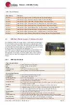
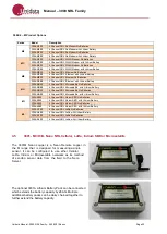
In the 3000 NRL Family some models are equipped with an LCD Display and keypad as standard, while
other models may have a display and keypad as an optional extra.
The logger status screen(s) enables the user to inspect the current status of a range of logger status
parameters. To access the logger status screen press the
ENTER
button (if the logger display is
sleeping) and then press the
LOGGER STATUS
button on the LCD touch display.
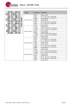
There are two streams of Logger Status data. You can toggle between these by again pressing the
LOGGER STATUS
button. The status values that can be displayed are as below: