


UC-00-M10 EN R1
Hardware Design
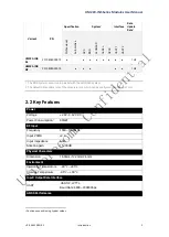
15
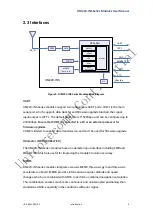
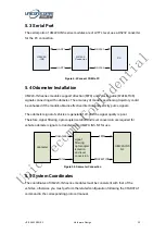
5.6
Installation of the Module
UM220-INS series modules must be rigidly connected to the vehicle body and firmly
fixed.
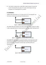
1. The antenna should be installed with the front facing up as much as possible and firmly fixed; ensure that
the elevation angle of the environment where the antenna is located is greater than 15 ° and the space is
unobstructed.
2. In the environment where the antenna is located, there is no strong interference source within the
frequency of 1568±20MHz.
5.6.1
Installation Instructions
The UM220-INS series modules must be firmly connected with the vehicle to prevent
any offsets or vibrations between the module and the vehicle. UM220-INS series
modules cannot be installed in the suspension part of the vehicle (with elastic part).
When the vehicle is moving, any change of the vehicle coordinate system will seriously
affect the UM220-INS module and prevent it from working normally.
5.6.2
Installation Angle Definition
The vehicle coordinate is RFU, and the module coordinate is xyz, as shown in figure 5-5
and figure 5-6. AngleR, angleF, and angleU of the module’s installation angle are defined
as below:
1.
Coincide the initial state of RFU coordinate with xyz coordinate’s
2.
Rotate γ angle of the module along the z axis
3.
Rotate angle of the module along the new x axis
4.
Rotate angle of the module along the new y axis
5.
The module is now in the same state as the actual installation, with that, angleR=
angleF=
angleU=