background image

8

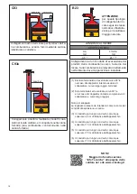
Per attivare solo la funzione antigelo posizio-

nare le due manopole come indicato in figura.

La Protezione antigelo è sempre attiva.

Anche disabilitando i servizi di riscaldamento e 

sanitario. 

MAX

M

IN

MAX

MIN

ATTENZIONE  (*)  vedi  avvertenze 

generali 1.1 

I modelli solo riscaldamento NON 

sono idonei alla produzione di acqua 

per il consumo umano secondo il 

D.M. 174/2004.

AttENZIONE!

QUALSIASI DANNO PROvOCAtO 

ALLA CALDAIA, DOvUtO ALLA 

FORMAZIONE DI INCROStAZIONI O 

DA ACQUE CORROSIvE, NON SARà 

COPERtO DA GARANZIA.

1.8 -  PROTEZIONE ANTIGELO 
 

DELLA CALDAIA

P

O

S

FUNZIONE ANtIGELO

 Alimentazioni

Hb (*)

Stato 

funzione

antigelo

Azioni

Elettrica

gas

1

ON

ON

< 6 °C

ON

- Bruciatore e Pompa ON fino a che T > 14°C

2

ON

Off

< 2 °C

ON

Solo quando alimentazioni entrambe ON:

- Bruciatore e Pompa OFF fino a che T > 5°C

- Quando T > 5°C allora Bruciatore e Pompa 

  ON fino a T > 14°C. 

Off

ON

Off

Off

(*) Sensore 11 par. 2.2

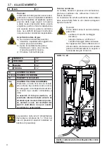
1.7 - TRATTAMENTO DELL’ACQUA

Il trattamento delle acque di alimen-

tazione consente di prevenire gli 

inconvenienti e mantenere funzio-

nalità  ed  efficienza  del  generatore 

nel tempo.

Il valore di pH ideale dell’acqua negli 

impianti di riscaldamento deve essere 

compreso:

Per minimizzare la corrosione, è 

fondamentale l’uso di un inibitore di 

corrosione, affinchè questo funzioni 

efficacemente, le superfici metalliche 

devono risultare pulite. 

(vedi listino domestico sez. ACCES

-

SORI di protezione impianti) 

Questa protezione puo’ intervenire 

solo se presenti alimentazione 

elettrica e gas.

Se una delle due viene a mancare e al 

ripristino


11 (SR)

  rileva una temperatura 

<  2  °C,  l’apparecchio  si  comporterà 

come descritto alla tab. 

pos 2.

L’impianto  di  riscaldamento  può 

essere efficacemente protetto dal gelo 

utilizzando prodotti antigelo con inibitore 

per Impianti di riscaldamento (specifici 

per multimetallo)

Non utilizzare prodotti antigelo per 

motori d’automobile perchè possono 

danneggiare le guarnizioni di tenuta 

acqua.

VALORE

MIN 

MAX

PH

6,5

8

Durezza [°fr]

9

15

NOtA!

Maggiori info nella sezione 

‘‘Info tecniche’’ alla pagina della

caldaia nel  sito www.unicalag.it

Содержание KON C 18

Страница 1: ...I TA L I A N O E N G L I S H R 18 C 18 R 24 C 24 R 28 C 28 R 35 C 35 ISTRUZIONI PER L INSTALLATORE E IL MANUTENTORE INSTALLATION AND SERVICING MANUAL ...

Страница 2: ...2 http www unicalag it prodotti domestico 50 condensazione gas 774 kon ...

Страница 3: ...e 28 4 2 Parametri modificabili da pannello comandi 30 4 3 Adattamento all utilizzo di altri gas 31 4 5 Schema elettrico 32 4 6 Codici di errore 33 3 ISTRUZIONI PER L INSTALLATORE 14 3 1 Avvertenze generali 14 3 2 Norme per l installazione 14 3 3 Operazioni preventive di verifica e adeguamento impianto 14 3 4 Imballo 15 3 5 Posizionamento della caldaia 16 3 6 Allacciamento condotto scarico fumi 17...

Страница 4: ...ll uso per il quale è stato espressamente previsto Ogni altro uso è da considerarsi improprio e quindi pericoloso 1 1 avvertenze generali Il libretto d istruzioni costituisce parte integrante ed essenziale del prodotto e dovrà essere conservato dall utente Leggere attentamente le avvertenze contenute nel libretto in quanto forniscono importanti indicazioni riguardanti la sicurezza di installazione...

Страница 5: ...istruzioni nonché gli altri documenti relativi all apparecchio inseriti nella busta contenuta nell imballo L utente deve custodire tale documentazione in modo da poterla avere a disposizione per ogni ulteriore consultazione Informare l utente sull importanza delle bocchette di areazione e del sistema di scarico fumi evidenziandone l indispensabilità e l assoluto divieto di modifica Informare l ute...

Страница 6: ...di alimentazione gas aria acqua e corrente elettrica al condotto fumi alla valvola di sicurezza e alla sua tubazione di scarico agli elementi costruttivi che influiscono sulla sicurezza operativa dell apparecchio Attenzione Per stringere o allentare i raccordi a vite utilizzare esclusivamente delle chiavi a forcella chiavi fisse adeguate L utilizzo non conforme e o gli attrezzi non adeguati posson...

Страница 7: ... 10 Pcond Potenza utile in condensazione 11 Qmax Portata termica massima 12 Adjusted Qn Regolata per portata termica nominale 13 PMS Pressione max esercizio riscaldamento 14 T max Temperatura max riscaldamento B Caratteristiche circuito sanitario 15 Qnw Portata termica nominale in funzione sanitario se diversa da Qn 16 D Portata specificaA C S secondo EN 625 EN 13203 1 17 R factor N rubinetti in b...

Страница 8: ...tamento delle acque di alimen tazione consente di prevenire gli inconvenienti e mantenere funzio nalità ed efficienza del generatore nel tempo Il valore di pH ideale dell acqua negli impianti di riscaldamento deve essere compreso Per minimizzare la corrosione è fondamentale l uso di un inibitore di corrosione affinchè questo funzioni efficacemente le superfici metalliche devono risultare pulite ve...

Страница 9: ...CHE TECNICHE E DIMENSIONI 2 1 CARATTERISTICHE TECNICHE 2 2 VISTA CON L INDICAZIONE DEI COMPONENTI PRINCIPALI E DIMENSIONI KON R 18 R 24 KON C 18 C 24 Vista dall alto Vista da sotto KON C 18 C 24 NOTA Per maggiori informazioni consultare Info Tecniche dal sito ...

Страница 10: ...10 KON R 28 R 35 KON C 28 C 35 Vista dall alto KON C 28 C 35 Vista da sotto ...

Страница 11: ...Rubinetto di scarico caldaia 15 Rubinetto di carico 16 Valvola deviatrice 17 Scambiatore a piastre 18 FL FH VM Ventilatore 19 AF AS PV Pressostato fumi 20 Valvola di sicurezza 21 By pass automatico 22 rb SRR Sensore di temperatura ritorno 23 tf TLC Termostato di sicurezza collettore fumi 24 Scambiatore Condensatore in alluminio 25 Valvola di sfiato 26 Sifone di scarico condensa C Uscita acqua cald...

Страница 12: ...IAGRAMMA PORTATA PRESSIONE DISPONIBILE PER L INSTALLAZIONE CIRCOLATORE MODULANTE OPTIONAL DIAGRAMMA PORTATA PRESSIONE DISPONIBILE PER L INSTALLAZIONE DIAGRAMMA PORTATA PRESSIONE DISPONIBILE PER L INSTALLAZIONE ...

Страница 13: ...5 Perdite al camino con bruciatore funzionante min max 1 4 2 4 1 4 2 8 1 9 2 4 1 9 2 8 Perdite al camino con bruciatore spento 0 60 0 46 0 41 0 34 Note Temperatura Ambiente 20 C Dati rilevati con apperecchio funzionante a Metano G20 KON R 18 C 18 R 24 C 24 R 28 C 28 R 35 C35 Categoria apparecchio II2H3P II2H3P II2H3P II2H3P Portata minima del circuito di riscald t 35 C l min 1 2 1 2 1 7 1 7 Pressi...

Страница 14: ...na fumaria Attenzione Se nel locale di installazione sono presenti polveri e o vapori aggressivi corrosivi l apparecchio deve essere adeguatamente protetto e deve poter funzionare indipendentemente dall aria del locale Attenzione Montare l apparecchio solo su una parete chiusa di materiale non infiam mabile piana verticale in modo che possano essere rispettate le distanze minime richieste per l in...

Страница 15: ...A declina ogni re sponsabilità nel caso di danni procurati a persone animali o cose subentranti in seguito a mancata osservanza di quanto sopra esposto H P L A B D C Nell imballo oltre all apparecchio sono contenute A BUSTA DOCUMENTAZIONE Libretto impianto Libretto istruzioni d uso per l utente Libretto istruzioni per l installatore e il manutentore Garanzia N 2 Cedole ricambi Certificato di confo...

Страница 16: ...ita da materiale infiammabile KON R C 18 R C 24 R C 28 R C 35 Poiché la temperatura della parete su cui è installata la caldaia e le temperatura del condotto di scarico coassiale non superano in funzionamento normale la temperatura ambiente di oltre 60 K non è necessa rio rispettare distanze minime da pareti infiammabili Per le caldaie a condotti di aspirazione e scarico sdoppiati nel caso di pare...

Страница 17: ...ti all esterno mediante condotti di tipo coassiale op pure di tipo sdoppiato C13 C33 PER CALDAIE A TIRAGGIO FORZATO Nel caso di sostituzione di caldaie sostituire SEMPRE anche il condotto fumi La caldaia è omologata per le configurazioni di sca rico sottoriportate LUNGHEZZA LINEARE SDOPPIATO Ø80 SDOPPIATO Ø60 DA m 2 FINO A m DA m 2 FINO A m 0 5 0 5 46 1 3 0 5 0 5 29 1 4 Condotti di aspirazione ari...

Страница 18: ... condotti coas siali nel locale caldaia e monoparete nella canna fumaria aria comburente controcorrente nella canna fumaria C83 C93x 1 Escluso terminale i ed eventuale curva 90 e nel caso di sdoppiati si intende escluso di sdoppiatore curve largo raggio terminali 2 Solo terminale i ed eventuale curva 90 e e nel caso di sdoppiati si intende comprensivo di sdoppiatore e curve largo raggio Nota per s...

Страница 19: ...ati Attenzione Per tutte le configurazioni di scarico montare il distanziale camino fornito con la caldaia Distanza tra condotto entrata aria e con dotto uscita fumi min 250 mm max 500 SISTEMA COASSIALE SISTEMA SDOPPIATO Per lunghezza LINEARE LL si intende senza curve terminali di scarico aspi razione e camino di scarico salvo specifiche indicazioni Lunghezza Lineare LL LL Lunghezza Lineare L1 L2 ...

Страница 20: ...O CALDAIA S cond SCARICO CONDENSA Rc RUBINETTO DI CARICO Svs SCARICO VALVOLA SICUREZZA Prevedere un tubo di scolo con imbuto ed un sifone che conducano ad uno sca rico adeguato in corrispondenza di Svs Lo scarico deve essere controllabile a vista In assenza di tale precauzione un eventuale intervento della valvola di sicurezza può causare danni a perso ne animali e cose nei confronti dei quali il ...

Страница 21: ...re al riempimento del circuito Tale operazione deve essere effettuata con cautela rispettando le seguenti fasi aprire le valvole di sfogo dei radiatori ed accertarsi del funzionamento della valvola automatica in caldaia aprire gradualmente il rubinetto di carico accer tandosi che le eventuali valvole di sfogo aria automatiche installate sull impianto funzionino regolarmente chiudere le valvole di ...

Страница 22: ...e è necessario installare sulla linea di alimentazione elettrica della caldaia un interruttore bipolare con distanza tra i contatti maggiore di 3 mm di facile accesso in modo tale da rendere veloci e sicure eventuali operazioni di manutenzione La sostituzione del cavo di alimentazio ne deve essere effettuata da personale tecnico autorizzato UNICAL AG S p A utilizzando esclusivamente ricambi origin...

Страница 23: ...ensa è stato riempito d acqua come indicato al capitolo 3 7 eventuali saracinesche di intercettazione impianto sono aperte il gas da utilizzare corrisponde a quello di taratura della caldaia in caso contrario provvedere ad effettuare la conversione della caldaia all utilizzo del gas disponibile vedi sezione 4 3 tale operazione deve essere eseguita da personale tecnico qualificato secondo le norme ...

Страница 24: ...ONE DELLA funzione di taratura 3 11 2 Posizionamento delle sonde 1 ATTIVAZIONE Premendo il pulsante D per 3 secondi si attiva la funzione taratura Rilasciare quando compare simbolo SERVICE Non premere x più di 9 par 4 2 Tale funzione non si attiva in presenza di blocco o richiesta sanitaria 2 MASSIMA POTENZA Girando la manopola B al MAX la caldaia fun zionerà alla massima potenza 3 simboli illumin...

Страница 25: ...i del terminale di aspirazione e scarico verificare che non vi siano perdite di gas 3 12 REGOLAZIONE DEL BRUCIATORE 2 Regolazione alla potenza minima Azionare la caldaia in modalità taratura alla MI NIMA POTENZA vedi 3 11 1 Una volta che il bruciatore è acceso controllare che il valore di CO2 MINIMO corrisponda a quello indicato nella tabella UGELLI PRESSIONI Correggere eventualmente il valore ruo...

Страница 26: ... 8 8 10 5 10 5 0 34 kg h 2 17 kg h 60 KON R 18 KON C 18 Tipo di Gas Potenza Utile kW Portata Termica kW risc Press Aliment mbar Velocità ventilatore rpm Diaframma collettore Ø n fori Livelli CO2 Consumi Consumi Potenza avviam IG min max min max min max Gas nat G20 2 9 17 4 3 0 18 20 1400 5700 9 5 9 5 0 32 m h 1 90 m h 50 Propano G31 4 2 17 4 4 4 18 37 1600 5300 11 2 11 2 0 34 kg h 1 40 kg h 35 KON...

Страница 27: ...il valore di Potenza percentuale del bruciatore 3 12 1 ADATTAMENTO DELLA POTENZA ALL IMPIANTO DI RISCALDAMENTO Es KON 24 per depotenziare la caldaia a 18 kW modificare il parametro HP circa 70 Agire sul parametro HP par 4 2 parametri modi ficabili da pannello comandi per ottenere il valore corrispondente alla potenza desiderata L utente NON è autorizzato all attivazione della funzione di seguito d...

Страница 28: ... di entrata dell acqua fredda se chiuse in precedenza Sfiatare e se necessario procedere al ripristino della pressione dell impianto di riscaldamento fino a raggiungere una pressione di 0 8 1 0 bar Aprire la valvola intercettazione gas Dare Tensione alla caldaia Controllare la tenuta stagna dell apparecchio sia sul lato gas che sul lato dell acqua Rimontare il mantello frontale dell apparecchio Is...

Страница 29: ...re a 0 4 bar Senza richiesta chiudere i rubinetti di intercettazione del circuito di riscaldamento apri re il rubinetto di scarico per far scendere la pressione d acqua Prima di rimettere in pressione verificare la pressione del vaso d espansione Vaso d espansione 8 Il vaso contiene la giusta quantità d aria Controllare la pressione d azoto 1 bar a caldaia vuota Rimette re in pressione la caldaia ...

Страница 30: ...30 TA 30 0 TA 0 POTENZA MASSIMA DI RISCALDAMENTO VALORI DA A STANDARD 0 Min 99 Max 99 PRERISCALDO VALORI DA A STANDARD 0 1 0 TEMPERATURA DELLA SONDA ESTERNA VALORI DA A STANDARD 0 20 C 30 10 C 20 0 C POST CIRCOLAZIONE DELLA POMPA VALORI DA A STANDARD 0 5 min 1 SEMPRE 0 5 min SELEZIONE Ruotare la manopola RISCALDAMENTO B MODIFICA VALORE Ruotare la manopola SANITARIO C Il valore lampeggia sul displa...

Страница 31: ... serbatoio del gas sia stato disaerato Per una disaerazione a regola d arte del serbatoio rivolgersi al fornitore dei gas liquido e comunque a personale abilitato ai sensi di legge Se il serbatoio non è stato disaerato a regola d arte possono insorgere problemi di accensione In tal caso rivolgersi al fornitore del serbatoio del gas liquido Per la conversione della caldaia da un gas all al tro occo...

Страница 32: ...ne FLS Flussostato richiesta sanitario MVD Motore valvola deviatrice P Circolatore SR Sensore riscaldamento mandata SRR Sensore riscaldamento ritorno SS Sonda sanitario Pred per modelli R TL Termostato limite TLC Termostato limite collettore fumi VG Valvola gas VM Ventilatore modulante SE Morsetti di collegamento Sonda esterna TA1 OT Morsetti di collegamento TA modulante TA2 Morsetti di collegamen...

Страница 33: ...nte sostituire la sonda esterna 14 1 SONDA DI RITORNO Sensore SRR ausiliario in terrotto Verificare il cablaggio even tualmente sostituire il sensore ausiliario 22 30 2 PARAMETRI DI SERVIZIO Parametri di servizio alterati a causa di eventuali interferenze elettromagnetiche Re impostare tramite il pannel lo e o regolafacile i parametri alterati 21 3 SCARSA CIRCOLAZIONE ACQUA Scarsa circolazione cir...

Страница 34: ...AMENTO SCAMBIATORE 24 Viene rilevato il congelamento dello scambiatore Se il sen sore riscaldamento rileva una temperatura inferiore a 2 C viene inibita l accensione del bruciatore fino a che il sensore rileva una temperatura supe riore a 5 C Togliere alimentazione elet trica chiudere il rubinetto del gas scongelare con attenzio ne lo scambiatore TERM LIMITE 11 TERMOSTATO SICUREZZA Intervento del ...

Страница 35: ...ccensione a freddo Agire su parametro IG mediante ausilio di REGOLAFACILE sezione MENU TECNICO parametri TSP aumentando il valore del 5 10 max KON 18 24 KON 28 35 Fiamma rumorosa a regime incrementare il valore della CO2 valore max per metano 9 8 valore min 9 2 valore max per propano 11 5 valore min 10 8 incrementare il valore della CO2 valore max per metano 9 6 valore min 9 1 valore max per propa...

Страница 36: ...2 http www unicalag it prodotti domestico 50 condensazione gas 774 kon ...

Страница 37: ...intenance instructions 28 4 2 Parameters that can be edited from the control panel 30 4 3 Adaptation to the use of other gas 31 4 5 Wiring diagram 32 4 6 Error codes 33 3 INSTALLATION INSTRUCTIONS 14 3 1 General warnings 14 3 2 Installation standards 14 3 3 Preventive system verification and adjustment operations 14 3 4 Packaging 15 3 5 Positioning the boiler 16 3 6 Flue gas exhaust pipe connectio...

Страница 38: ...it was expressly designed Any other use is to be considered improper and therefore dangerous 1 1 general warnings The instruction booklet is an integral and essential part of the product and must be kept by the user Read the warnings contained in this instruction booklet carefully as they provide important guidelines regarding installation use and maintenance safety Keep the booklet with care for ...

Страница 39: ...ing the appliance inserted in the envelope inside the packaging The user must keep this documentation safe for future consultation Inform the user about the importance of the air vents and the flue gas exhaust system high lighting their essential features and the absolute prohibition of modifying them Inform the user concerning controlling the system s water pressure as well as operations to resto...

Страница 40: ...ete Do not modify the following parts the boiler the gas air water and electricity supply lines the flue gas pipe the safety valve and the exhaust pipe the construction parts which affect the operating safety of the appliance Attention To tighten or loosen the screwed fittings use only appropriate fixed spanners Incompliant use and or inappropriate tools can cause damage e g water or gas leakage A...

Страница 41: ...condensation 11 Qmax Maximum heat output 12 Adjusted Qn Adjusted for rated heat output 13 PMS Max heating operating pressure 14 T max Max heating temperature B Domestic hot water circuit characteristics 15 Qnw Rated heat output in domestic hot water func tion if different to Qn 16 D Specific D H W flow rate according to EN 625 EN 13203 1 17 R factor No of taps according to the declared amount of w...

Страница 42: ... OFF Sensor 11 par 2 2 1 7 WATER TREATMENT The treatment of the supply water allows to prevent inconveniences and maintain the functionality and efficiency of the generator over time The ideal water pH in heating systems must be within To minimise corrosion it is crucial to use a corrosion inhibitor in order for it to work properly the metal surfac es must be clean see system protection ACCESSO RI...

Страница 43: ... AND DIMENSIONS 2 1 TECHNICAL FEATURES 2 2 VIEW WITH THE INDICATION OF THE MAIN COMPONENTS AND DIMENSIONS KON R 18 R 24 KON C 18 C 24 View from above View from below KON C 18 C 24 NOTE For further details refer to the Technical Information from the website ...

Страница 44: ...10 KON R 28 R 35 KON C 28 C 35 View from above KON C 28 C 35 View from below ...

Страница 45: ...ficiency pressure switch 14 Boiler drain valve 15 Filling valve 16 Diverter valve 17 Plate heat exchanger 18 FL FH VM Fan 19 AF AS PV Flue gas pressure switch 20 Safety valve 21 Automatic by pass 22 rb SRR Return temperature sensor 23 tf TLC Flue gas collector safety ther mostat 24 Aluminium Heat Exchanger Ca pacitor 25 Vent valve 26 Condensation drain trap C Domestic hot water outlet G G Gas inle...

Страница 46: ...R INSTALLATION OPTIONAL MODULATING PUMP DIAGRAM OF FLOW RATE PRESSURE AVAILABLE FOR INSTALLATION DIAGRAM OF FLOW RATE PRESSURE AVAILABLE FOR INSTALLATION Flow rate l h Flow rate l h Avaible Head m c a metres of water Avaible Head m c a metres of water ...

Страница 47: ...5 Heat loss at chimney with burner on min max 1 4 2 4 1 4 2 8 1 9 2 4 1 9 2 8 Heat loss at chimney with burner off 0 60 0 46 0 41 0 34 Notes Room Temperature 20 C Data detected with appliance running on Methane gas G20 KON R 18 C 18 R 24 C 24 R 28 C 28 R 35 C35 Appliance category II2H3P II2H3P II2H3P II2H3P Minimum heat circuit output t 35 C l min 1 2 1 2 1 7 1 7 Minimum heating circuit pressure b...

Страница 48: ...ere are aggressive corrosive vapours present in the installation room the appliance must be protected suitably and must be able to operate independently from the air in the room Attention Only mount the appliance on a closed wall made of non flammable materi al flat vertical so that the minimum distances required for installation and maintenance can be observed The boiler must be connected to a ce...

Страница 49: ... will not be held liable for damage to persons animals or ob jects due to failure to comply with the instruction above H P L A B D C As well as the appliance the packaging contains A DOCUMENTATION ENVELOPE System booklet User operating instructions booklet Instruction booklet for the installer and maintenance engineer Warranty 2 Spare parts form Certificate of conformity Gas conversion label B Con...

Страница 50: ...e of flammable material KON R C 18 R C 24 R C 28 R C 35 Since the temperature of the wall on which the boil er is installed and the temperature of the coaxial exhaust pipe do not exceed in normal operating conditions a room temperature beyond 60 K it is not necessary to observe the minimum distances from flammable walls For boilers with double intake and exhaust pipes in the event of crossing flam...

Страница 51: ...xial or double pipes C13 C33 FOR BOILERS WITH FORCED DRAUGHT In the event the boiler is replaced ALWAYS re place the flue gas pipe as well The boiler is type approved for the exhaust configu rations listed below 1 Excluding terminal s and possible 90 bend and in the event of double pipes it means excluding splitter wide radius bends terminals 2 Only terminal s and possible 90 bend and in the event...

Страница 52: ...ue must comply with standards in force C63 Boiler intended for connection to a combustion air intake and combustion products evacuation system approved and sold separately ATTENTION for this type of con nection the room follows the same in stallation rules for boilers with natural draught NOTE Further details in the section Technical Information on the boiler page of the www unicalag it website Co...

Страница 53: ...double systems Attention For all drain configurations mount the chimney spacer supplied with the boiler Distance between air inlet pipe and flue gas exhaust pipe min 250 mm max 500 COAXIAL SYSTEM DOUBLE SYSTEM By LINEAR length LL one means with out bends exhaust intake terminals and exhaust chimney unless specified otherwise Linear Length LL LL Linear Length L1 L2 NOTE For further details relating...

Страница 54: ...ONDENSATION DRAIN Rc FILLING VALVE Svs SAFETY VALVE DRAIN Provide a drain pipe with funnel and a trap that lead to a suitable drain in cor respondence of Svs This drainage must be controlled on sight If this precaution is not taken trigger ing of the safety valve can cause dam age to persons animals and objects for which the manufacturer cannot be held responsible Condensation drain The boiler dur...

Страница 55: ...ed the circuit can be filled This operation must be performed carefully respect ing the following phases open the radiator vent valves and make sure the automatic valve is working properly in the boiler open the filling tap gradually making sure that the automatic air release valves installed on the system work properly close the radiator air release valves as soon as water comes out check the pre...

Страница 56: ...fter having removed the jumper ON OFF room thermostat connection RT OT Remember that a bipolar switch must be installed on the boiler power line with over 3 mm between contacts easy to access making maintenance quick and safe The power cable must be replaced by technical personnel authorised by UNI CAL AG S p A using original spare parts only Failure to comply with the above can jeopardise the saf...

Страница 57: ...p stopped Has the condensation drain trap been filled with water as indicated in chapter 3 7 are any system shut off gate valves open does the gas to be used correspond to the boiler calibration gas otherwise perform the boiler conversion in order to use the gas available see section 4 3 this operation must be carried out by technical staff qualified in compliance with the standards in force is th...

Страница 58: ...ON OF THE calibration function 3 11 2 Positioning the probes 1 ACTIVATION By pressing the button D for 3 seconds the calibration function is activated Release it when the SERVICE symbol appears Do not press it for more than 9 par 4 2 This function is not activat ed if there is a block or domestic hot water request 2 MAXIMUM OUTPUT By turning the knob B onto MAX the boiler will operate at maximum o...

Страница 59: ...ake and exhaust terminal check that there are no gas leaks 3 12 ADJUSTING THE BURNER 2 Minimum output adjustment Operate the boiler in calibration mode at MINI MUM OUTPUT see 3 11 1 Once the burner is on check that the CO2 MINI MUM value corresponds to that indicated in the table NOZZLES PRESSURE Correct it if needed by turning with a screwdriver the screw R CLOCKWISE to increase it ANTI CLOCKWISE...

Страница 60: ... 5900 9 8 8 10 5 10 5 0 34 kg h 2 17 kg h 60 KON R 18 KON C 18 Type of Gas Effective Output kW Heating Thermal kW Capacity Supply Press mbar Fan speed rpm Collector diaphragm Ø n holes CO2 levels Con sumption Con sumption Start up power IG min max min max min max Nat gas G20 2 9 17 4 3 0 18 20 1400 5700 9 5 9 5 0 32 m h 1 90 m h 50 Propane G31 4 2 17 4 4 4 18 37 1600 5300 11 2 11 2 0 34 kg h 1 40 ...

Страница 61: ...e by decreasing the burner output value 3 12 1 ADAPTATION OF THE POWER TO THE HEATING SYSTEM E g KON 24 to decrease the output of the boiler to 18 kW edit parameter HP about 70 Act on parameter HP par 4 2 parameters that can be edited from control panel to achieve the value corresponding to the desired output The user is NOT authorised to activate the func tion described below ...

Страница 62: ...d previously Vent and if necessary restore the heating pres sure until reaching a pressure of 0 8 1 0 bar Open the gas shut off valve Switch the boiler on Make sure the appliance is gas tight and water tight Remount the front casing of the appliance Failure to perform Inspections and Main tenance can entail material and personal damage TABLE OF RESISTANCE VALUES ACCORDING TO THE TEMPERATURE TO THE...

Страница 63: ...itch block the boiler if the water pressure is below 0 4 bar Without request close the shut off valves of the heating circuit open the drain valve to make the water pressure decrease Before pressurising again check the pressure of the expansion vessel Expansion vessel 8 Does the vessel contain the right amount of air Check the nitrogen pressure 1 bar when the boiler is empty Pressurise the boiler ...

Страница 64: ... TA 30 0 TA 0 MAXIMUM HEATING OUTPUT VALUES FROM TO DEFAULT 0 Min 99 Max 99 PREHEATING VALUES FROM TO DEFAULT 0 1 0 EXTERNAL PROBE TEMPERATURE VALUES FROM TO DEFAULT 0 20 C 30 10 C 20 0 C PUMP POST CIRCULATION VALUES FROM TO DEFAULT 0 5 min 1 ALWAYS 0 5 min SELECTION Turn the HEATING knob B EDITING THE VALUE Turn the DOMESTIC HOT WATER knob C The value flashes on the display CONFIRM SELECTION Conf...

Страница 65: ...efore installing the appli ance For state of the art deaeration of the tank contact the LPG supplier or a person qualified in compliance with law If the tank has not been professionally deaerated ignition problems could arise In that case contact the supplier of the LPG tank To convert the boiler from one type of gas to another proceed as follows Disconnect the appliance from the elctrical power s...

Страница 66: ...lectrode FLS Domestic hot water request flow switch MVD Diverter valve motor P Pump SR Flow heating sensor SRR Return heating sensor SS Domestic hot water probe Pred for R models TL Limit thermostat TLC Flue gas collector limit thermostat VG Gas valve VM Modulating fan SE External probe connection terminals TA1 OT Modulating TA connection terminals TA2 On off TA connection terminals ...

Страница 67: ... wiring if needed replace the external probe 14 1 RETURN PROBE Auxiliary SRR sensor inter rupted Check the wiring if needed re place the auxiliary sensor 22 30 2 SERVICE PARAMETERS Service parameters altered due to possible electromagnetic interferences Reset the altered parameters via the panel and or regola facile 21 3 POOR WATER CIRCULATION Poor circulation in primary circuit Check pump operati...

Страница 68: ...EXCHANGER FREEZING 24 Exchanger freezing is detected If the heating sensor detects a temperature below 2 C burn er ignition is inhibited until the sensor detects a temperature above 5 C Disconnect the from the power supply close the gas valve defrost the exchanger carefully LIMIT THERM 11 SAFETY THERMOSTAT Intervention of the safety ther mostat 10 Press the unblock button on the panel and or check...

Страница 69: ...Act on parameter IG using the REGOLAFACILE section TECHNICAL MENU TSP parameters increasing the value by 5 10 max KON 18 24 KON 28 35 Flame noisy in steady state conditions increase the CO2 value max value for methane gas 9 8 min value 9 2 max value for propane 11 5 min value 10 8 increase the CO2 value max value for methane gas 9 6 min value 9 1 max value for propane 11 0 min value 10 3 Flame noi...

Страница 70: ......

Страница 71: ......

Страница 72: ...enziali Unical declines every responsibility for the possible inaccuracies if owed to errors of transcript or press Also reserves the right to bring those changes that it will hold necessary to it own products or profits without jeopardizing its essential characteristics 46033 casteldario mantova italia tel 39 0376 57001 fax 39 0376 660556 info unical ag com export unical ag com www unical eu AG S...

Отзывы: