Unical ALKON 28 R HE Скачать руководство пользователя страница 40

40

Codes fault

5

The symbol           flashes on the display when the boiler detects a fault.

1) In case of a fault which does not causes the stop of boiler operation, to show the error code it is necessary
to press the reset push button. If the boiler is in stand-by the error code appears in the display also without
pressing the reset push button.

2) In case of an error code which causes the stop of boiler operation, the error code is shown directly on the
display in flashing mode.
Each error is characterized by a priority level: if two errors are detected at the same time, the error code with
higher priority is shown.Here below the list of the known errors.

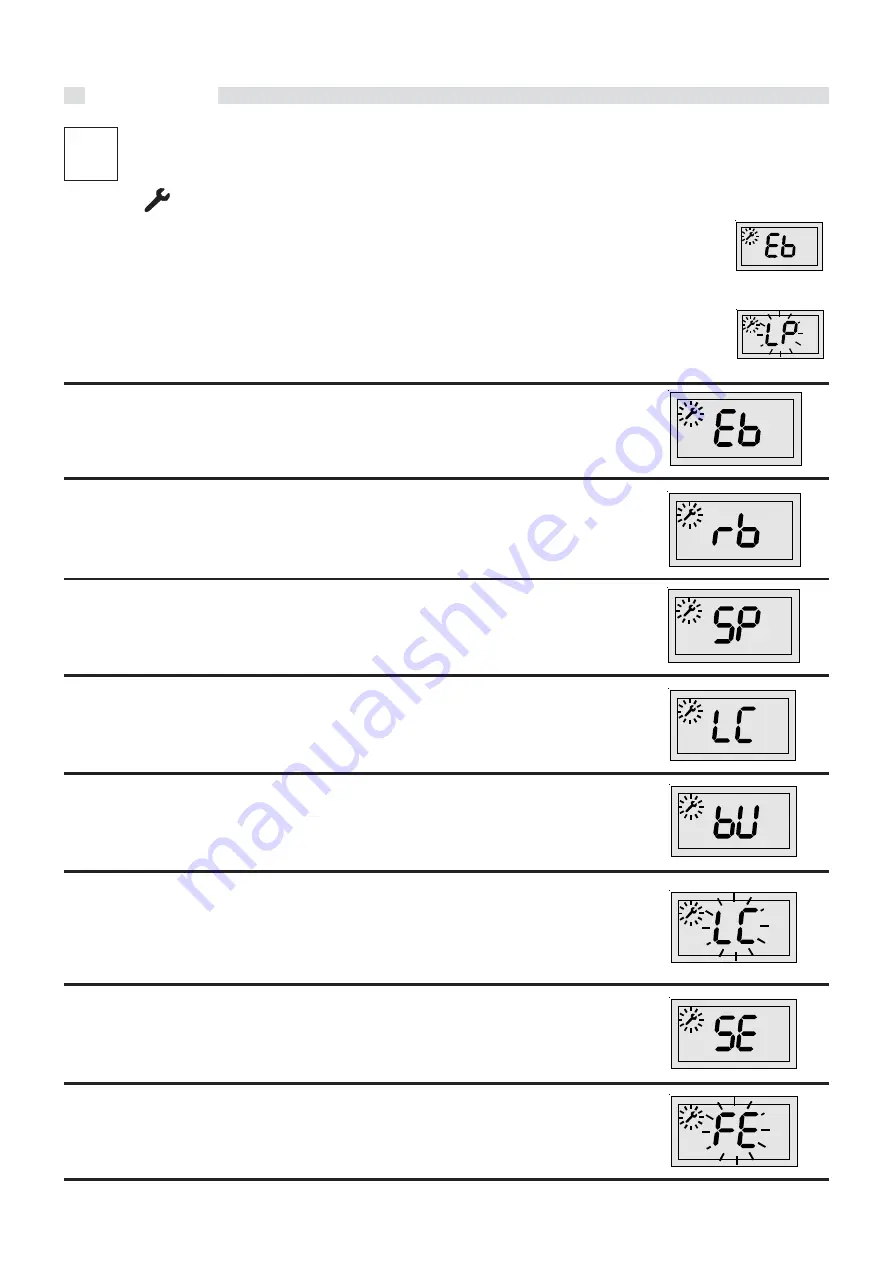
Outer temperature sensor (priority 0)

Description:

Outer temperaturesensor interrupted

Possible solutions:

Inspect the harness; if necessary replace the outer sensor

.

Heating return temperature sensor (priority 1)

Description:

Return temperature sensor interrupted

Possible solutions:

Inspect the harness; if necessary replace the return temperature sensor

.

Working parameters (priority 2)

Description:

Working parameters corrupted

Possible solutions:

Re-introduce the correct working parameters.

Insufficient circulation (priority 3)

Description:

Insufficient circulation in the primary circuit

Possible solutions:

Inspect the operation of the pump and its speed adjustment

Mistension supply to the burner (priority 4)

Description:

It depends on the electrical supply (Frequency and Voltage out of the standard limits)

Possible solutions:

Wait for the values entering within the limits

Heating flow and return temperature sensors (priority 5)

Description:

Water circulation through primary circuit 

very

 weak

Possible solutions:

Inspect the operation of the pump and its speed setting; remove possible obstructions of the
C.H. system; clean the possible fouled D.H.W. heat exchanger.

Heating flow and return temperature sensors (priority 6)

Description:

Heating flow and return temperature sensors inverted

Possible solutions:

Inspect the harness

Fan (priority 7)

Description:

Alteration of the fan speed

Possible solutions:

Inspect the operation of the fan and its harness.

°C

°C

°C

°C

°C

°C

°C

°C

°C

°C

FAULT CODES

Содержание ALKON 28 R HE

Страница 1: ...INSTALLATION AND SERVICING MANUAL 00333883 2nd edition 06 2012 ALKON 28 R HE 28 C HE 35 R HE 35 C HE...

Страница 2: ...14 Electrical connections 25 Connection to mains supply 230V 25 Outdoor sensor connection 26 ON OFF digital room controller connection 27 Layout of the electrical connection for zone control systems 2...

Страница 3: ...ar as possible to the one you really require We recommend you to check the state of cleanliness of the domestic hot water heat exchanger at the end of the first year and subsequently on the basis of t...

Страница 4: ...tructive components which influence the appliance s safe operation WARNING When tightening or loosening the screw pipe connections use only adequate fork spanners The improper use and or the use of in...

Страница 5: ...N 13203 1 18 F factor N stars based on the quality of water declared EN 13203 1 19 PMW Max pressure D H W system 20 T max Max temperature D H W system C Electrical features 21 Electrical power supply...

Страница 6: ...ing turn off the electrical supply to the boiler by means of the ON OFF switch and or by means of the appropriate shutdown devices Do not obstruct the inlet outlet terminals In the event of failure an...

Страница 7: ...ectronic ignition Flame modulation in function of the absorbed power Minimum heat output adjustment in CH mode Electronic adjustment of the ignition ramp Electronic frost protection mode Pump overrun...

Страница 8: ...drain siphon 2 Domestic hot water temperature sensor 3 Aluminium heat exchanger condenser 4 Flow temperature sensor 5 Overheat safety thermostat 6 Ignition Ionisation electrode 7 Air vent valve 8 Flue...

Страница 9: ...ter pressure switch 11 Return temperature sensor 12 Expansion vessel 13 Circulation pump 14 Flow temperature sensor 15 By Pass 16 Manometer 17 Central heating circuit safety valve 18 System drain cock...

Страница 10: ...30 8 1 148 6 2 0 5 6 15 14 9 82 11 1 12 6 14 7 17 7 35 60 230 50 4 133 X5D 46 28 C HE II2H3P 2 17 0 5 2 5 2 5 85 30 8 1 148 6 2 0 5 6 12 5 12 8 69 9 8 11 2 13 15 6 35 60 230 50 4 133 X5D 46 Heat outpu...

Страница 11: ...gas type available This is verifiable via the indication on the packaging and on the data badge c Check that the chimney flue pipe has an adequate draught does not have any constrictions and that no...

Страница 12: ...assume the responsibility of complying to all the local and or national regulations published in the official publications as well as all the applicable codes of practice The installation must be car...

Страница 13: ...ied with a paper Wall mounting template which facilitates the connection of the gas and water feed pipes when laying out the hydraulic system and before installing the boiler This template has to be f...

Страница 14: ...een carried out For fitting the boiler Place the steel mounting template on to the wall Determine the position of the holes for fixing the support bracket Drill the holes and fix the support bracket u...

Страница 15: ...rging of the system Ensure yourself that the system s piping is not used as earth clamps for the electrical or telephonic system They are absolutely unsuitable for this use In a short time this could...

Страница 16: ...pressure in the system must be between 1 and 2 5 bar if the pressure is higher fit a reducing pressure valve WARNING The hardness of the mains water supply conditions the frequency with which the DHW...

Страница 17: ...ced a siphon must be fitted supplied with the boiler there must be no bottlenecks the connection must be made just under the bottom part of the boiler it must be installed so as to avoid freezing of t...

Страница 18: ...ope of this treatment is finalized for eliminating or substantially reducing the following problems lime scale deposit corrosion sludge deposits microbiological growths moulds bacteria etc An appropri...

Страница 19: ...ntric or twin ducts The minimum distance between the air inlet duct and the flue gas outlet duct must be of 250 mm and moreover both terminals must be positioned within a 500 mm square area C43 Boiler...

Страница 20: ...pipes is of 0 75 metres The maximum allowable length of the horizontal concentric pipes is of 3 5 metres For each elbow added the maximum length permitted has to be reduced by 1 metre HORIZONTAL FLUE...

Страница 21: ...ion so as to enable the collection of any condensate formed in the boiler Type C33 The maximum allowable length of the vertical concentric pipes is of 8 5 metres including the terminal 80 125 For each...

Страница 22: ...0 mm It is not permitted to position the two terminals on opposite walls The maximum pressure loss permitted independently from the type of installation must not exceed the value of 100 Pa 00361435 KI...

Страница 23: ...ES OF THE COMBUSTION AIR INLET PRODUCTS OUTLET DUCTS When calculating the pressure losses bear in mind the following parameters For the twin flue pipe system s adaptor the pressure loss is of 4 Pa For...

Страница 24: ...in the combustion product outlet For the 60 L 1 horizontal combustion air inlet terminal the pressure loss is of 6 Pa For the 60 L 1 horizontal combustion products outlet terminal the pressure loss i...

Страница 25: ...both poles in an easy accessible position so as to ensure quick and safe servicing The replacement of the supply cable as to be carried out by a qualified authorized UNICAL engineer using only origin...

Страница 26: ...rresponds to the minimum design temperature The minimum flow temperature instead HL is automatically set by the boiler when the outdoor temperature is 20 C Once these parameters have been set the boil...

Страница 27: ...tion optional Get access to the terminal strip M1 Connect the leads coming from REGOLAFACILE to the terminals 3 4 of terminal strip M1 Remove the link between terminals 1 2 DANGER Switch off and disco...

Страница 28: ...anding heat when the diverter valve reaches the low temperature position and sends the request to the boiler The 3 way valve has to use the limit switch contact in order to simulate this type of reque...

Страница 29: ...I L S E O T T A A 1 4 A 1 5 B L A C K B L A C K W H I T E W H I T E Y E L L O W Y E L L O W B L A C K A 7 A 1 6 A 1 8 A 1 7 L I G H T B L U E B R O W N Y E L G R E E N N L 1 L I G H T B L U E B R O W...

Страница 30: ...ature sensor OT Terminals for Modulating Room Thermostat REGOLAFACILE TA Terminals for ON OFF Room Thermostat Note The figures shown on the above wiring diagram are purely indicative JP1 selection typ...

Страница 31: ...products example anti freeze solutions for motor vehicles or use wrong concentrations of anti corrosion solutions This could cause damage to the washers and could provoke noise during normal boiler op...

Страница 32: ...or installer 3 17 INITIAL LIGHTING PRELIMIARY CHECKS The first ignition must be carried out by a qualified technician Failure to do so could cause injury to persons animals or damage to property UNIC...

Страница 33: ...C C To enter the parameters push and keep pressed for ten seconds the reset button release when the flashing wrench appe ars on the display MAX M I N Rotate the HEATING temperature adjustment knob B t...

Страница 34: ...nd the combustion analysis can be performed Maximum output symbol wrench steady and symbol radiator steady MAX M I N MAX M I N C C Operation at the minimum output Rotate the HEATING temperature adjust...

Страница 35: ...n mode by rotating the HEATING knob B to its MAX setting and then press the RESET push button for 3 s symbol wrench steady ON and symbol radiator steady ON Check that the C02 values are within the val...

Страница 36: ...5 5 6 5 6 30 10 ALKON R 28 HE C 28 HE 9 2 10 1 6400 6400 20 37 0 58 m h 0 43 kg h 2 96 m h 2 17 kg h Nat gas G20 LPG G31 1700 1700 9 2 10 2 5 6 5 6 50 10 INCONVENIENTS SOLUTIONS Noisy flame at cold s...

Страница 37: ...14 16 18 20 22 24 26 28 30 32 34 36 38 40 0 5 10 15 20 25 30 35 40 45 50 55 60 65 70 ALKON R 28 HE C 28 HE 0 2 4 6 8 01 12 14 16 18 20 22 24 26 28 30 32 34 36 38 40 0 5 10 15 20 25 30 35 40 45 50 55...

Страница 38: ...boiler The frequency of servicing will be determined by the service engineer and will depend on the appliance s state of condition These adjustments can be performed only by Service Centres authorized...

Страница 39: ...annually Check every 2 years Check efficiency of fan s operation Test for gas soundness Clean the burner and check the ignition efficiency Clean the condensate drain siphon and check that it is disch...

Страница 40: ...replace the return temperature sensor Working parameters priority 2 Description Working parameters corrupted Possible solutions Re introduce the correct working parameters Insufficient circulation pr...

Страница 41: ...tion of the D H W temperature sensor if applicable Possible solutions Check the sensor for good operation see table Resistance Temperature and or its harness C H flow temperature sensor priority 13 De...

Страница 42: ......

Страница 43: ......

Страница 44: ...tial characteristics Directions for proper disposal of the product according to Directive 2002 96 EC At the end of its life the product must not be disposed of as municipal waste It can be taken to a...

Отзывы: