background image

User’s Manual                                                                                                                                                                       and UT5320R-SxA Series 


4 / 43


Instruments.uni-trend.com


Do Not 
open the outer shell 

Please do not open the outer shell of withstand tester. Only qualified 
maintenance personnel can open the outer shell. The instrument is still 
has unreleased electric charge for a period after power off, it may cause 
electric shock to person. 

Do Not 
operate  the  instrument  when  it  is 
abnormal 

If the instrument can not work properly, the dangerous is unpredictable. 
Please cut off the power wire and do not use the instrument. Do not 
attempt to fix it by yourself. 

Do Not 
operate  the  instrument  out  of  the 
requirement of the manual 

If  operate  the  instrument  out  of  the  requirement  specified  in  this 
manual, the protective for the instrument will be failure. 
It is strictly prohibited to use this equipment on life support system or 
any other equipment with safety requirements.     

Do Not 
replace  the  component  or  execute 
unauthorized modification 

In  order  to  guarantee  the  safety  of  this  instrument,  please  do  not 
replace the component or execute any unauthorized modification. 
Do not operate the instrument if the outer shell is removerd or loose. 

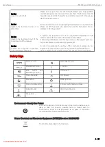
Safety Sign


Direct Current 


Netrual/Zero Line


Alternating Current


Live Line


Both 

Direct 

and 

Alternating Current


ON (Power)


Three Phase AC


OFF(Power)


Grounding


Backup Power


Protective Grounding


Connect with Cabinet or Case


Signal Ground


Warning or Caution


Dengerous


Environment-friendly Use Period 


EFUP is the period of time before any of the RoHS substances are 
likely  to  leak  out,  causing  possible  harm  to  health  and  the 
environment.  EFUP  of  this  instrument  is  40  years,  it  should  be 
recycling system when exceed 40 years. 


Waste Electrical and Electronic Equipment (WEEE) Directive 2002/96/EC 


Must not be discarded in the trash can. 

Содержание UT5300X+ Series

Страница 1: ...User s Manual UT5300X and UT5320R SxA Series 1 43 Instruments uni trend com User s Manual UT5300X and UT5320R SxA Series Programmable Hipot Tester ...

Страница 2: ...ate of the original purchase from UNI T or an authorized UNl T distributor Power cords accessories and fuses etc are not included in this warranty If the product is proved to be defective within the warranty period UNI T reserves the rights to either repair the defective product without charging of parts and labor or exchange the defected product to a working equivalent product determined by UNI T...

Страница 3: ...ct special occasional or inevitable damage in advance they assume no responsibility for such damage Safety Precautions Warning Dangerous Pleasefollowthefollowingguidelinestoavoidpossibleelectricshockandrisktopersonal safety Users must follow the following conventional safety precautions in operation service and maintenance of this device UNI T will not be liable for any personal safety and propert...

Страница 4: ...to use this equipment on life support system or any other equipment with safety requirements Do Not replace the component or execute unauthorized modification In order to guarantee the safety of this instrument please do not replace the component or execute any unauthorized modification Do not operate the instrument if the outer shell is removerd or loose Safety Sign Direct Current Netrual Zero Li...

Страница 5: ...ot be used between operator and DUT When design the workdfiled it is not allowed that the operator across the DUT to operating the test instrument The workplace should be tidy and clean Unused instrument and test wire should put in a fixed position make sure that all personnel can immediately distinguish the parts under test to be tested and tested The test station and its surrounding can not have...

Страница 6: ...ltmeter They may be damaged if their output terminals are subject to an external voltage The output port connect to the external voltage may cause damage to the instrument 1 4 To Ensure Long Term Use without Failures It is recommend to use the instrument in the range as follows Ambient Temperature Maximum Output Power Pause Time Limited Output Time T 40 AC Withstand Voltage 12mA UT5320R S4A S8A 6m...

Страница 7: ...nel UT5320R S4A AC DC IR programmable hipot tester 20 mA four channels UT5320R S8A AC DC IR programmable hipot tester 20 mA eight channels UT5310A can provide withstand voltage test 5 kVAC 10 mA UT5310D can provide withstand voltage test 5 kVAC 10 mA and 6 kVDC 5mA UT5310R can provide withstand voltage test 5 kVAC 10 mA 6 kVDC 5mA and insulation resistance test 2 5 kVDC 10 GΩ UT5320R can provide w...

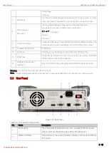
Страница 8: ...ce This series equipped with Handler PLC interface for industrial control RS485 option RS 232C and LAN interface for PC connection and supports SCPI and Modbus RTU communication protocols to efficiently complete remote control and data acquisition functions so the instrument can suitable for the needs of multiple different automatic test system 2 2 Front Panel Figure 1 2 1 Front Panel Take UT5320R...

Страница 9: ...l Model label 11 STOP key STOP key is to stop the test or cancle the hint of PASS FAIL 12 START key START key is to start the test once the test is running CAUTION START indicator light will be sparkling 13 Multiple channel s scan interface Only for UT5320R S4A 4 channels and UT5320R S8A 8 channels Warning Do not touch the test port during the test Note If apply an external voltage to the test por...

Страница 10: ...ST 4 LAN interface Connect when using a LAN interface Only for UT5310R 20R S4A S8A 5 RS 232C interface RS 485 interface option Serial communication interface is to communicate with the PC 6 Protective ground terminal Chassis ground terminal Before operating the instrument please make sure that the ground is properly connected 7 AC 220 110 adaptor Voltage scale switch of AC the instrument is only s...

Страница 11: ... 10 mA single channel UT5320R AC DC IR programmable hipot tester 20 mA single channel UT5320R S4A AC DC IR programmable hipot tester 20 mA four channels UT5320R S8A AC DC IR programmable hipot tester 20 mA eight channels 2 Inspect appendix for the list of accessories If any of the accessories are missing or damaged please contact UNI T or local distributors of this product Item Quantity Remarks Pr...

Страница 12: ... under overvoltage class Ⅲ and Ⅳ Before start the power please make sure that power voltage is conform to AC SELECTOR on the rear panel of the instrument Input Voltage Frequency Range Fuse Model Rated Power 110 V 47 63 Hz 5 A UT5320R S4A S8A 400 VA 110 V 3 A UT5310A D R 300 VA 220 V 3 15 A UT5320R S4A S8A 400 VA 220 V 2 A UT5310A D R 300 VA Warning In order to prevent the electric shock please con...

Страница 13: ...internal of the instrument 3 6 Power on 3 6 1 Initial Power on After confirm the instrument is intact and installed in properly please inspect it as the following steps 1 Only connect the power cable of the instrument and not connect other test wires and then turn on the tester s power switch 2 After the instrument enters the measurement interface press START key directly to test the test status s...

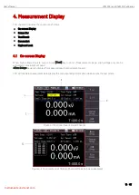
Страница 14: ...n Display When high voltage stops to output press Test key to enter Measurement page High voltage only can be activated in measurement page Meas Setup page is to display the measured result and judement result LCD will divide into several areas to display the corresponding information when enters the test mode Figure 4 1 Test Interface of Single Channel Figure 4 2 Test Interface of Multiple Channe...

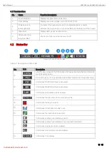
Страница 15: ... Icon of Status Bar Table 4 1 Description of Status Bar No Icon Description START boot up key on the front panel it s only activated when start mode is local in system setup PLC boot up key it s only activated when start mode is PLC in system setup It indicates RS 232 interface is activated It indicates RS 485 interface is activated It indicates LAN interface is activated It indicates the file nam...

Страница 16: ...t greater than 999 9s 3 Judgement of test result a For the withstand voltage test the test result of the upper lower limit of striking current can be judged at any time b For the insulation resistance test it will judge the result when the test time is near to close 4 Description table of failed test and abnormal protection Judgement Result Description Over the upper limit It indicates the measure...

Страница 17: ...t is FAT32 maximum capacity 128G 4 5 Lock Keyboard In order to prevent to change the test condition accidentally the instrument has lock keyboard function Short press Lock key on the panel to lock the keyboard long press 1s Lock key to unlock the keyboard a In system setup when adjustable mode is disabled the instrument is only respond to START STOP and LOCK key when the keyboard is locked b In sy...

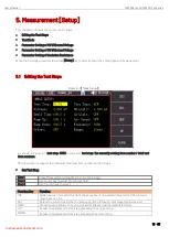
Страница 18: ...he currently setting item number total test item numbers The instrument is support the maximum total test item numbers are 20 steps Set Test Step Step 1 Press Measurment Setup key to enter setup page Step 2 Use cursor key to select Test Step field Step 3 Use function key to select Function Key Function INS Add a new test item after this item the sequency of new added item and the following item mo...

Страница 19: ...oltage test HI Limit 0 001 20 00 mA 1mA UT5320R S4A S8A the upper limit of striking current alarm 0 001 10 00 mA UT5310A D R the upper limit of striking current alarm LO Limit 0 001 mA the upper limit OFF OFF The lower limit of striking current alarm Dwell Time 0 1 999 9 s continous test 0 5 s Test time of the currently setting item Ramp Up 0 1 999 9 s 0 5 s Rated voltage to rising slowly based on...

Страница 20: ...re and to zero clearing At this point DUT must be removed from the test line Press OFF key to clear 5 4 Parameter Setting of DC Withanstand Voltage Figure 5 3 Meas Setup Item Input Range Default Value Description Volatge 0 050 6 000 kV 0 060 kV Output voltage during DC withstand voltage test HI Limit 0 1uA 10 00 mA 1 mA UT5320R S4A S8A the upper limit of striking current alarm 0 1uA 5 00 mA UT5310...

Страница 21: ...disabled DC withstand voltage test will not judge the value of current test whether is over the upper limit of striking current alarm Wait 0 1 999 9 s OFF OFF Waiting time of DC charge waiting time to the judgement of the upper lower limit of the current Rising time the set value of waiting judement time rising time test time Charge LO OFF Manual input 0 1 350 uA auto test OFF The setting of the m...

Страница 22: ... aims to shorten the test time It is the best way for sorting test Charge Lo OFF manual input 0 1 350 uA auto test OFF The setting of the minimum charge current It is used to detect the test wire or test fixture whether is normal connected to make sure the correctness of the test result Since the leakage current is usually quite small during the insulation resistance test so the lower limit of lea...

Страница 23: ...as Setup 3 Item Input Range Default Value Description Voltage 0 050 0 500 kV 0 100 kV Output voltage during touch inspecting test Except in special circumstances use the default setting in general LO Limit 0 1uA 1 00 mA 500 uA The lower limit of touch inspecting alarm Except in special circumstances use the default setting in general Scan Setup ON OFF OFF UT5320R S4A can control channel 1 2 3 4 UT...

Страница 24: ...ts multi channel test wires are double wire ports Each channel s port of the double wire port has two lead outputs of which the thicker plug is the high voltage lead during the test the thinner plug is the current sampling lead during the test A resistance of more than 1MΩ is built in between the two lines which is used as the self test standard of the port In general two lines must be short circu...

Страница 25: ...re 6 1 System Setup 1 Page Table 6 1 Explaination of SYSTEM 1 Page Item Input Range Default Value Description Start mode Local PLC Local Local Pressstartkey on the frontpanel to boot up PLC Input START control signal by HANDLER to boot up Communication It a always valid the specific refer to the communication protocol Volume Low middle high Middle The volume setting of beeper Key sound ON OFF ON T...

Страница 26: ...which is failed Next step Stop the current test and press START key to start the next step Disp mode All the last step P F All Select All mode When performe a multi step test the test results of All will displayed after the test is finished The display is as follows toggle the up and down cursor key to switch the display Select The last step mode When perform a single test or multi step test the t...

Страница 27: ...abled and the test is failed press START key to continue the test Ctrl mode File single step File File When file test is finished HANDLER interface outputs the test result Single Step After each step is finished HANDLER interface outputs the test result of the current step Pass Hold 0 1 99 9 s key control Key control 0 1 99 9 s When the test is qualified hold time of the qualified judgment Key con...

Страница 28: ...t Range Default Vaule Description Language English Chinese Chinese Select the language for the instrument Date time The instrument is adopt 24 hours clock use this key to modify date and time Remote RS232 RS485 LAN RS232 The instrument supports three interfaces RS232 RS485 and LAN Protocol SCPI MODBUS SCPI The instrument supports two communication protocols SCPI and Modbus RTU it usually use SCPI ...

Страница 29: ...the test from running unless the safety lock pin on the signal I O port connector is short circuitted Attached pluggable terminal can be used for this purpose to facilitate wiring The detailes refer to Chapter 8 2 IP addr 192 168 001 123 When communication mode is TCP use numeric keyboard to change the parameter Port 502 It is the default value and cannot be change It will be used when the communi...

Страница 30: ...d Boot up recall function can assign the call file when the instrument is boot up it has two options file 1 and the current file If select the file 1 then load the setting value of file 1 when the instrument is boot up The setting steps 1 Enter File page 2 Use cursor key to select Auto load filed 3 According to the need to select file 1 or the current file by the function key on the screen 7 1 3 F...

Страница 31: ...ion Press up or down direction key to select and display the character support long press Press ENTER key to confirm the change press ESE key to cancle the change 7 1 5 Recall File Copy It s convenient for user to quickly batch set the instrument and the instrument supports save the setting information to external U flash disk Other instrument can read the required parameter from U flash disk U fl...

Страница 32: ...g cause error action and dangerous STOP key can be operate it s to turn off high voltage output at anywhere Table8 1 Definition of HANDLER Input Output Pin Name Function Description Signal input 1 COM common low end It provides 0V signal for start and stop 3 START signal The instrument starts the test when START is short circuited with COM 4 RESET STOP signal The instrument stop the test when STAR...

Страница 33: ...instrument is testing After the test is completed the relay will return PIN2 and PIN5 to the open circuit state Signal output test is pass When DUT test is pass relay will connect PIN8 and PIN9 and hold the state When other test program starts to test or press the stop swith relay will return PIN8 and PIN9 to the open circuit state Signal output test is failed When DUT test is failed relay will co...

Страница 34: ...tage about 24V please confirm it befor using The maximum transient current cannot be greater than 0 5A and the long term working current cannot be greater than 0 2A If a larger current is required please prepare a power supply 2 3 pin and 4 pin of SIGNAL interface is online lock signal System Setup 2 page if Safety Lock function is enabled then online lock signal should provide by the external Onl...

Страница 35: ...that each bit should via a data line to transmit But the configuration of most serial ports is usually not strictly based on the RS 232 standard a 25 core connector is used in each port today s computers basically use a 9 core connector The common RS 232 signal as shown in the following table Table 9 1 Common RS 232 Signal Signal Symbol Pin number of 25 core connector Pin number of 9 core connecto...

Страница 36: ...nstrument Transmit mode full duplex asynchronous communication with start and stop bit Baud rate Baud Rate setting in System Setup 2 page Data bit 8 bits Stop bit 1 bit Parity bit no 9 2 RS 485 Interface Setting The instrument selects RS485 interface and support ModBus RTU protocol The instrument s station number can set to 1 32 in System Setup2 station number of multi salve is different RS485 is ...

Страница 37: ...D Illuined connecting Blinking communicating Orange LED Extinguished 10BASE T Illuined 100BASE TX 9 3 1 Select LAN Communication Mode Move cursor to Communication Mode field use function key to select LAN 9 3 2 Set IP Address Move cursor to Communication Mode field use function key to select Then use numeric keyboard to input And then press ENTER key to confirm the change press ESE key is to cancl...

Страница 38: ...ut Voltage AC Voltage Rnge 0 050kV 5 000kV 0 050kV 5 000kV Voltage Wave Sine wave Sine wave Distortion 3 3 Operating Frequency 50 60Hz optional 50 60Hz optional Accuracy of Frequency 1 1 Output Power 50VA 5 000kV 10mA 100VA 5 000kV 20mA Regulated rate of Voltage 1 0 50V rated power 1 0 50V rated power DC Voltage range 0 050 kV 6 000kV 0 050 kV 6 000kV Frequency of Signal Source 600Hz 600Hz Output ...

Страница 39: ...uracy of Current 2 0 Reading 5 characters 2 0 Reading 5 characters Actucal Current OFF 0 001 mA 10mA OFF 0 001 mA 20mA DC Current Range 0 1uA 5 00mA 0 1uA 10 00mA Accuracy of Current 2 0 Reading 5 characters 2 0 Reading 5 characters Discharge Automaically discharge after the test is finished Automaically discharge after the test is finished Insulation Resistance Test Output Voltage 0 050kV 2 500kV...

Страница 40: ...0GΩ 10mA 0 1 MΩ 0 5 MΩ 2mA 0 5 MΩ 5 MΩ 200uA 5 MΩ 50 MΩ 20uA 50 MΩ 500 MΩ 2uA 500 MΩ 10GΩ Test Accuracy of Resistance 500V 1MΩ 1GΩ 5 Reading 5 characters 1GΩ 10GΩ 10 Reading 5 characters 500V 0 2MΩ 1GΩ 10 Reading 5 characters 1GΩ 10GΩonly for reference no requirements 500V 1MΩ 1GΩ 5 Reading 5 characters 1GΩ 10GΩ 10 Reading 5 characters 500V 0 1MΩ 1GΩ 10 Reading 5 characters 1GΩ 10GΩ only for refer...

Страница 41: ...iting time Test Time 0 1s 999 9s When in TIMER ON Accuracy of Time 0 2 Setting 0 1s Measurement Function Keyboard Lock Preventing accidental modification of test condition or forbid the test condition from being modified Zero Clearing Current flowing through the insulation resistance and distributed capacitance between the output lines can be cleared to zero Boot up Delay When start to test press ...

Страница 42: ... Power Supply 100V 121V 198V 242V 47 5 63Hz Power Loss UT5310x Series 300VA UT5320x Series 400VA Size 280mm 88mm 428mm UT5310A D R 20R 280mm 138mm 428mm UT5320R S4A S8A Weight of Instrument UT5310A D R About 10 7kg UT5320R About 12 9kg UT5320R S4A About 16 27kg UT5320R S8A About 16 87kg Gross Weight of Standard Package UT5310A D R About 13 8kg UT5320R About 16 0kg UT5320R S4A About 20 12kg UT5320R...

Страница 43: ...User s Manual UT5300X and UT5320R SxA Series 43 43 Instruments uni trend com ...

Отзывы: