P/N:110401104397X
5. Rotary knob set to CONTINUITY: to measure low resistance.
6. Rotary knob set to 250V/500V/1000V:
to select test voltage for insulation resistance measurement.
If low battery indicator shows on upper left corner of LCD after the
meter is turned on, it means battery is almost used up and need to
be replaced.
Low battery indicator
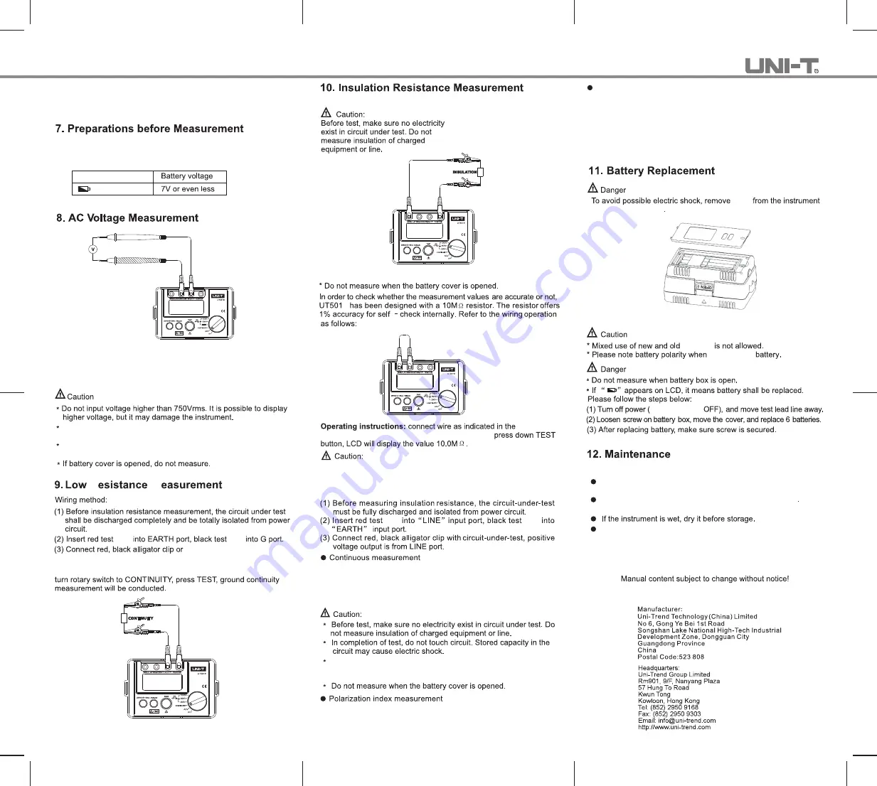
(See Figure 1)
Figure 1
(1) Set the rotary switch to ACV.
(2) Insert the red test lead into "V" jack and the black test lead
into "G" jack.
Please take extreme caution in order to avoid electric shock when
measuring high voltage.
Disconnect test leads and tested circuits and remove test leads
away from input jacks after completing the measurement.
(See Figure 2)
lead
lead
test probe with the circuit
under test.
With the instrument connected to tested circuit as described above,
Figure 2
(See Figure 3)
Figure 3
B
(See Figure 4)
Figure 4
figure 4,
then switch to any insulation measurement range,
Do not short-circuit the test leads under high-voltage output status
or make insulation measurement after high voltage has already
been output.
●
Turn the knob to select test voltage 250V/500V/1000V.
lead
lead
With the knob already set to test voltage 250V/500V/1000V, then
press TEST button,the instrument will be self-locked to measure
continuously. The test voltage will be output and TEST button will
light up. With the measurement finished, press TEST button to
unlock and stop the measurement.
When red and black clips are connected to the circuit under test,
high voltage is output from LINE jack and the current from
EARTH jack.
Under insulation measurement mode, press PI/DAR button once
to select PI parameter, the screen displays Time 1(1min)/Time2
(10mins), then press TEST to start PI measurement.
Cleaning the housing
Clean the instrument surface with soft cloth or sponge
dampened with clean water.
To avoid damage to the instrument, do not submerge it into
the water.
When it is necessary to verify or repair instrument, please
deliver the instrument to qualified professional serviceman
or designated repairing department.
the knob set to
batteries
installing the
Figure 5
wires
when replacing battery.
(See Figure 5)
Dielectric absorption ratio measurement
Under insulation measurement mode, press PI/DAR button two
times to select DAR parameter, the screen displays Time 1(30s)/
Time2(1min), then press TEST to start DAR measurement, then
press TEST three times to select another DAR, the screen shows
Time 1(15s)/Time2(1min), press to begin another DAR
measurement.
R
M
*END*


