UNI-T UT-P4000 Series Скачать руководство пользователя страница 10


10


Under certain circumstances, oscillation may occur if the probe is connected to the power 
supply while the power supply is on. This does not indicate a malfunction. Oscillation can 
be stopped and operation restored to normal by opening and closing the sensor head. 


Depending on the measured current frequency, some sound maybe produced by resonance, 
but has no effect on measurements. 


The reading may be affected by the position within the clamp aperture of the conductor 
being measured. The conductor should be in the center of the clamp aperture. 


When carrying out a measurement, press the opening lever until the UNLOCK indication 
disappears and check that the sensor head is properly closed. If the sensor head is not 
properly closed, an accurate measurement is not possible. 


Accurate measurement may be impossible in locations subject to strong external magnetic 
fields, such as transformers and high-current conductors, or in locations subject to strong 
external electric fields, such as radio transmission equipment. 


At high frequencies, common mode noise may affect measurements taken on the high 
voltage side of circuits. If this occurs, reduce the frequency range of the waveform 
measuring instrument or clamp onto the low-voltage side of the circuit. 

5.


  Accessories Description 


BNC Cable: 100cm, MALE X MALE


Power Adapter (12V/1A)


6.


  Specification 

6.1 Electrical characteristics 
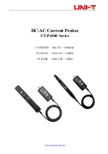
Model 

UT-P4030D 

UT-P4150 

UT-P4500 

Bandwidth(-3dB) 

DC-100MHz 

(Figure1) 

DC-12MHz 

(Figure4) 

DC-5MHz 

(Figure7) 

Содержание UT-P4000 Series

Страница 1: ...www uni trend com DC AC Current Probes UT P4000 Series UT P4030D 30A DC 100MHz UT P4150 150A DC 12MHz UT P4500 500A DC 5MHz...

Страница 2: ...ss of important data Do not proceed beyond a CAUTION notice until the indicated conditions are fully understood and met A WARNING notice denotes a hazard It calls attention to an operating procedure p...

Страница 3: ...istics 10 6 2 Mechanical characteristic 13 6 3 Environmental characteristic 14 7 Operating Method 14 7 1 Preparation before testing 15 7 2 Degaussing and Zero setting 15 7 3 Measuring method 15 8 The...

Страница 4: ...capabilities Over current protection with dual indicators buzzer and LED High and low range selection Low current measurements Degaussing and automatic zero setting Digital set by panel soft push key...

Страница 5: ...ul during measurement 2 Opening lever The operating lever used to open the sensor head Pull the lever to open the sensor jaw put in the cable under test and push the lever to lock the sensor head to m...

Страница 6: ...Model Range Transfer ratio UT P4030D 30A 0 1V A 5A 1V A UT P4150 150A 0 01V A 30A 0 1V A UT P4500 500A 0 01V A 75A 0 1V A 10 Power supply socket External power supply socket standard with 12V 1A adap...

Страница 7: ...the sensor head Align the sensor so that the probe s current direction indication corresponds to the direction of current flow through the conductor to be measured Also align the clamp so that the co...

Страница 8: ...it from vibration or shock during transport and handling and be especially careful to avoid dropping Do not store or use the device where it could be exposed to direct sunlight high temperature humidi...

Страница 9: ...ontinuous maximum continuous input for an extended period of time may result in activation of the safety circuit to prevent damage resulting from heating of the sensor At high ambient temperatures the...

Страница 10: ...pears and check that the sensor head is properly closed If the sensor head is not properly closed an accurate measurement is not possible Accurate measurement may be impossible in locations subject to...

Страница 11: ...0A 300Ap 500A 750A Current transfer ratio 5A 1V A 30A 0 1V A 75A 0 1V A 30A 0 1V A 150A 0 01V A 500A 0 01V A Measurable current 5A 1mA 30A 10mA 75A 10mA 30A 10mA 150A 100mA 500A 100mA Amplitude accura...

Страница 12: ...e2 UT P4030D Figure3 UT P4030D Continuous maximum input measurement Input impedance VS Frequency curve Figure4 UT P4150 Amp Frequency curve Figure5 UT P4150 Figure6 UT P4150 Continuous maximum input m...

Страница 13: ...put impedance VS Frequency curve 6 2 Mechanical characteristic Model UT P4030D UT P4150 UT P4500 Measurement conductor diameter max 5mm 20mm Cable length 1m 1 5m BNC Cable length 100cm Adapter dimensi...

Страница 14: ...voltage might deviate because of the surrounding temperature so please be careful when testing sequentially The frequency of the current under test may cause resonance but this won t influence the tes...

Страница 15: ...the high frequency current probe UT P4000 series adapter and oscilloscope Power up the UT P4000 probe and the green LED power indicator will be lighted Set the oscilloscope Ground the measuring mode...

Страница 16: ...powered by standard adapter independent of oscilloscope power so it is very easy to use 9 2 Can UT P4000 series product measure small current A Yes For now the UT P4000 series current probe has two o...

Страница 17: ...nt because the probe is not on the circuit yet The current under test should not surpass the limit value of the probe Please always maintain your probe and do not use it in the humid environment If th...

Отзывы: