background image


UDP6720 Series Digital Control Power Supply 

User’s Manual 


20 


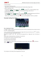
Count Configuration Table of List Mode 

Table setting

serial number of each group is corresponding to voltage, current and time value, push rotary knob 

  to 

set parameter; 

Voltage

adjust the actual output voltage value


Current

adjust the current value


Time

duration output time value in this serial number


: operating status at the current, push rotary knob 

  to switch mode


Save: save the setting parameter for powerdown function, push rotary knob 

  to save the current setting; 

  : clear parameter values in the table all to zero (voltage 00.00, current 00.00, time 00.00), push rotary knob 

  to eliminate the setting parameter values in the table; 

Notice: clear select function is eliminate the corresponding group of origin point to count. 


Parameter Setting of Delayer Mode 


Interface of Delayer Mode 


It presents power output status and delayer time of user configuration

it’s convenient to view the data. 


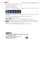
Protection setting

this function can set protection value of voltage, current and power, push rotary knob 


select 

“√”

to turn on protection function


Cycle index

It divide into maximum inf and 1-999. A cycle period is start form setup origin point to end point; 

Count

It  can  set  “001”  -  “048”,  which  is  excute  group  from  origin  point  to  end  point.  Push  rotary  knob 

  to 

adjusting parameter;   

Origin point: It can adjust 

000

-

047

, which is start from origin point to run. Push rotary knob 

    to adjusting 

parameter (“origin point” value + “count” value 

  048) 

Mode: It divide into three mode stop, run and pasue, it can not set


Содержание UDP6720 Series

Страница 1: ...UDP6720 Series Digital Control Power Supply User s Manual ...

Страница 2: ...r cords accessories and fuses etc are not included in this warranty If the product is proved to be defective within the warranty period UNI T reserves the rights to either repair the defective product without charging of parts and labor or exchange the defected product to a working equivalent product determined by UNI T Replacement parts modules and products may be brand new or perform at the same...

Страница 3: ...r whether UNI T and its distributors are informed of any possible indirect special occasional or inevitable damage in advance they assume no responsibility for such damage Safety Information Warning Caution To avoid possible electric shock and personal safety problem please follow the instructions below Disclaimer Please read the following safety information carefully beforestarting to use the ins...

Страница 4: ...sive atmosphere Do not use the instrument in flammable and explosive gas steam or dusty environment The use of any electronic equipment in such an environment is a risk to personal safety Safety Mark Grounding On Power Protective Grounding Off Power Signal Ground Connect with Cabinet or Case Dangerous Mark Environment friendly Use Period EFUP is the period of time before any of the RoHS substances...

Страница 5: ...ice ratio Storage for 3x200 preset voltage and current output Basic Performance UDP6721 UDP6721 digital control power supply with widest voltage and current range it can applied in many fields Take UDP6720 for example with max power 100W and ouput adjustable in 60V 5A auto control voltage and current slew rate power rate up to three times rapid than other similar products One instrument can replac...

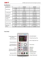
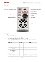
Страница 6: ... 0 01 5mV Current 0 01 3mA 0 01 5mA Power Supply Regulation Voltage 0 01 3mV 0 01 5mV Current 0 1 3mA 0 1 5mA Programming Accuracy Voltage 0 05 10mV 0 05 10mV Current 0 2 2mA 0 3 5mA Read back Accuracy Voltage 0 05 10mV 0 05 10mV Current 0 1 2mA 0 3 5mA Ripple and Noise Voltage 2 0mV rms 5 0mV rms Current 5 0mA rms 8 0mA rms Dimension W H D 87 174 255 mm 87 174 255 mm Weight Net 2 5Kg 2 5Kg Front ...

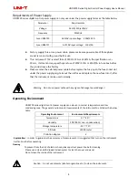
Страница 7: ...rm that accessories has no loss If there have any problem please contact with Uni Trend Instrument Sale Department or the distributor Components Quantity Remarks The instrument 1 The model is subject to the actual order 3C power line 1 250V 3 15A spare fuse UDP6720 1 250V 5A spare fuse UDP6721 1 Alligator cips with parallerl wire 1 User s Manual Upper computer software 1 Electronic file download f...

Страница 8: ... plug take out the old fuse and replace the new fuse into it after that the instrument can be used normally Warning Do not use power cable with any signs of damage to avoid danger Operating Environment UDP6720 series digital control power supply can only use in normal termperature and low condensing zone The general environmental requirements of the instruments is listed as the below table Operati...

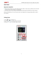
Страница 9: ...ent Sale Department or the distributor 2 Confirm whether the AC input voltage of UDP6720 UDP6721 comply with the standards of your country or region Notice Use 110V 220V switch on the rear panel to select input voltage After confirming the above matters power on the instrument Voltage Setup 1 Push key to set voltage value 2 Push or to select the specific numeric field 3 Rotating to enter the defin...

Страница 10: ...ing to enter the definited current parameter 1 2 3 Enable Output 1 Push to enable power output function and the indicator light will be green In the mean time C V C C indicator light will be green or red light according to the different output mode 2 OUTPUT key indicator light will be off when OUTPUT function is disable C V C C indicator light will also be off ...

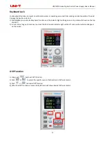
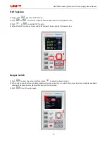
Страница 11: ...nction and the indicator light will be green Lock symbol will shown on the top of screen 2 In lock status long push Lock key to unlock the function and indicator light will be off Lock symbol will also disappear on the screen OVP Function 1 Long push key to set OVP function 2 Push or to select the specific numeric field and enter OVP parameters 3 Push or to enable OVP function 4 When the OVP funct...

Страница 12: ... enable OCP function 4 When the OCP function set successfully mark will shown beside OCP parameters 1 2 3 Bepper Switch 1 Push to enter the setup interface rotate to adjusting buzzer mode 2 When the buzzer function is enable keyboard sound is also turn on when the buzzer function is disable keuboard sound will be silent Buzzer status will shown on the top screen 3 Push to exit the setup page 3 ...

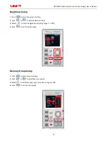
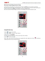
Страница 13: ... interface 2 Push or to select Brightness field 3 Rotate to set the brightness adjusting range 0 100 4 Push to exit the setup page 1 2 3 Memory Group Setup 1 Push to enter setup interface 2 Push or to select Memory option 3 Rotate to set memory group the maximum range is 200 4 Push to exit the setup page ...

Страница 14: ...ry key M1 M3 to call the specific stored output voltage current When user call the stored output voltage current the corresponding memory key will indicate green light Output Mode Setup 1 Push to enter setup interface 2 Push or to select the output status bar 3 Rotate to select Out State 4 Output status symbol will shown on the top screen when output is finished 5 Push to exit the setup page Notic...

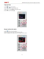
Страница 15: ...sh or to select language field 3 Rotate to select Languge type English Chinese 4 Push to exit the setup page Display Interface Information 1 Push to enter the setup interface 2 Use left right arrow key to select the IO Information option 3 RS232 configuration information will shown on the right side of the screen ...

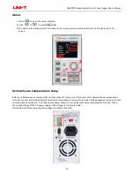
Страница 16: ...p Before use Remote Sense compensation function take off short connect terminal on the Remote Sense compensation terminal connect load voltage positive terminal to compensation terminal S and load voltage negative terminal connect to compensation terminal S And then enable power output to turn on Remote Sense compensation function That is the output voltage of the DC power supply is the voltage of...

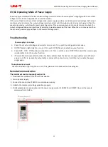
Страница 17: ...tage and current is zero or not If it is reset the voltage and crrent value 2 OUTPUT indicator light is light on or not If it is push OUTPUT key to enable the output function 3 Check OVP OCP OTP function is activated or not If it is reset the value of OVP OCP and wait the power supply remain stable to turn the output function 4 If Remote Sense compensation function has been enabled check the line ...

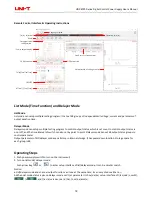
Страница 18: ...ontrol output status which is set count to control output status is on or off and the time interval of switch can also set by point to point Delayer mode can set 48 output status groups to control parameter Output parameter of list delayer mode can all store in internal storage It has powerdown function Storage space for each group is 48 Operating Steps 1 Push power supply switch to turn on the in...

Страница 19: ...of List Mode Interface of List Mode Menu introduction of list mode Cycle index It divide into maximum inf and 1 999 A cycle period is start form setup origin point to end point Push rotary knob to adjusting parameters Count It can set 001 048 which is excute group from origin point to end point Push rotary knob to adjusting point Notice each voltage current and time is a point Origin point It can ...

Страница 20: ...er values in the table Notice clear select function is eliminate the corresponding group of origin point to count Parameter Setting of Delayer Mode Interface of Delayer Mode It presents power output status and delayer time of user configuration it s convenient to view the data Protection setting this function can set protection value of voltage current and power push rotary knob select to turn on ...

Страница 21: ...lay time push rotary knob to set parameter Mode ON presents output function is enabled OFF presents output function is disabled Time set the delay time of the main interface operating status at the current push rotary knob to switch mode Save save the setting parameter for powerdown function push rotary knob to save the current setting clear parameter values in the table all to zero voltage 00 00 ...

Отзывы: