background image

PL

DE

RO

Bedienungsanleitung

Instrukcja obsługi

Manual de utilizare

EN

 User's manual

Digital 

clamp 

multimeter

MIE0146 

Содержание MIE0146

Страница 1: ...PL DE RO Bedienungsanleitung Instrukcja obsługi Manual de utilizare EN User s manual Digital clamp multimeter MIE0146 ...

Страница 2: ......

Страница 3: ...e das Gehäuse Verwenden Sie nicht das Messgerät wenn es beschädigt ist oder das Gehäuse oder einen Teil davon entfernt ist Achten Sie auf Risse oder fehlende Kunststoffteile Achten Sie auf die Isolierung der Anschlüsse Kontrollieren Sie die Messleitungen auf beschädigte Isolierung oder freiliegendes Metall Überprüfen Sie die Messleitungen auf Durchgang Ersetzen Sie beschädigte Messleitungen mit id...

Страница 4: ...tladen Sie alle Hochspannungskon densatoren vor Widerstands Durchgangs und Diodentest Tauschen Sie die Batterie so bald die Batterie Anzeige erscheint Mit einer schwa chen Batterie kann das Messgerät falsche Messwerte anzeigen die zu Stromschlag oder Verletzungen führen können Bei der Wartung des Messgeräts verwenden Sie nur das gleiche Modell Nummer oder Ersatzteile mit identischen elektrischen S...

Страница 5: ...ansformatorzangen Loslassen des Hebels schließt die Zange 6 Handschutz verhindert das Berühren von gefährlichen Zonen mit der Hand 7 Transformatorzangen Aufnehmen des Wechselstroms der durch den Leiter fließt Umwandlung von Strom in Spannung Der getestete Leiter muss vertikal durch den Zangenzentrum gehen AUFBAU DES MESSGERÄTES Abb 1 ...

Страница 6: ... Sie während 10 Minuten keine Taste drücken Das Messgerät kann durch drücken einer beliebigen Taste aktiviert werden siehe Wirksamkeit der Funktion stasten und kehrt zur Anzeige der zuvor gewählten Funktion zurück 5 SUMMER Der Summer ertönt bei jedem Tastendruck Wenn das Messgerät in 1 Minute in den Schlafmodus schaltet ertönt fünfmal ein Piepton Vor dem Umschalten in den Schlaf modus ertönt nochm...

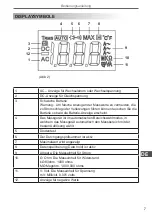
Страница 7: ...d die Batterie Anzeige erscheint 4 Das Messgerät ist im automatischen Bereichswahlmodus in welchem das Messgerät automatisch den Messbereich mit der besten Auflösung wählt 5 Diodentest 6 Der Durchgangsprüfsummer ist aktiv 7 Maximalwert wird angezeigt 8 Datenspeicherung Data hold ist aktiv 9 Ampere Die Messeinheit für Strom 10 Ω Ohm Die Messeinheit für Widerstand kΩ Kilohm 1000 ohms MΩ Megohm 1 000...

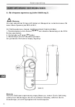
Страница 8: ...Rote Messleitung an die Buchse und schwarze Messleitung an die COM Buchse anschließen 2 Drehschalter auf Position stellen 3 Messleitungen an die Prüfschaltung anlegen Der gemessene Wert wird im Display angezeigt DURCHFÜHRUNG DER MESSUNGEN Hinweis Wenn die Gleichspannungsmessung abgeschlossen ist trennen Sie die Verbindung zwischen den Messleitungen und der zu prüfenden Schaltung entfernen Sie die ...

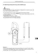
Страница 9: ...schließen 1 Rote Messleitung an die Buchse und schwarze Messleitung an die COM Buchse anschließen 2 Drehschalter auf Position V stellen 3 Messleitungen an die Prüfschaltung anlegen Der gemessene Wert wird im Display angezeigt Hinweis Wenn die Wechselspannungsmessung abgeschlossen ist trennen Sie die Verbind ung zwischen den Messleitungen und der zu prüfenden Schaltung entfernen Sie die Messleitung...

Страница 10: ...uchse anschließen 2 Drehschalter auf Position stellen Widerstandsmessung Ω ist voreingestellt oder drücken Sie die Auswahltaste SELECT für Modus Widerstandsmessung 3 Messleitungen an die Prüfschaltung anlegen Der gemessene Wert wird im Display angezeigt Hinweis Durch Entfernen der Komponenten von der Prüfschaltung können genauere Messergebnisse erzielt werden Wenn die Widerstandsmessung abgeschlos...

Страница 11: ...chließen 2 Drehschalter auf Position stellen und drücken Sie die Auswahltaste SE LECT für Messmodus 3 Zur Messung der Durchlassspannung des Halbleiters die rote Messleitung an die Anode und die schwarze Messleitung an die Kathode des Halbleiters anlegen Hinweis Durch Entfernen der Komponenten von der Prüfschaltung können genauere Messergebnisse erzielt werden Wenn die Diodenmessung abgeschlossen i...

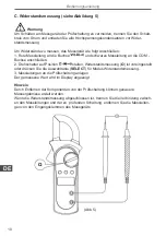
Страница 12: ...uchse und schwarze Messleitung an die COM Buchse anschließen 2 Drehschalter auf Position stellen und drücken Sie die Auswahltaste SE LECT für Messmodus 3 Der Summer ertönt wenn der Widerstand einer Schaltung kleiner als 10Ω ist 4 Der Summer ertönt oder auch nicht wenn der Widerstand der Schaltung größer als 10Ω ist Hinweis Wenn die Durchgangsprüfung abgeschlossen ist trennen Sie die Verbindung zwi...

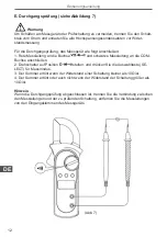
Страница 13: ...Strommessung durchzuführen gehen Sie wie folgt vor 1 Drehschalter auf Position 20A 200A oder 600A stellen 2 Drücken Sie den Auslöser zum öffnen der Transformatorzangen 3 Stromleitung vertikal durchs Zangenzentrum führen und Hebel langsam loslas sen bis die Zange geschlossen ist Vergewissern Sie sich dass die Leitung sich im Zentrum der Zange befindet anderenfalls können die Messergebnisse abweiche...

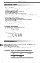
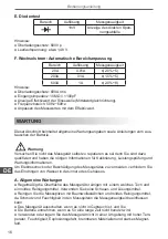
Страница 14: ...mversorgung 9V Batterie Schlafmodus kann ausgeschaltet werden Abmessungen 76mm x 208mm x 30mm Gewicht etwa 260g Batterie eingeschlossen B Umgebungsbedingungen Das Gerät ist für den Innengebrauch vorgesehen Höhengrenze Betrieb 2000m Lagerung 10000m Verschmutzungsgrad 2 Temperatur und Feuchtigkeit Bedienung 00 C 300 C 75 R H 300 C 400 C 70 R H 400 C 500 C 45 R H Lagerung 200 C 600 C 75 R H TECHNISCH...

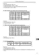
Страница 15: ...0V 100mV 600V 1V 1 3 Hinweise Überladungsschutz 600V rms Eingangsimpedanz 10MΩ C Widerstand Automatische Bereichanpassung Bereich Auflösung Messgenauigkeit 200Ω 100mΩ 1 2 2 2kΩ 1Ω 1 2 20kΩ 10Ω 200kΩ 100Ω 2MΩ 1kΩ 1 2 2 20MΩ 10kΩ 1 5 2 Hinweise Überladungsschutz 600V p D Durchgangsprüfung Bereich Auflösung Messgenauigkeit 100mΩ Bei 10Ω ertönt ein Piepton Hinweise Überladungsschutz 600V p Leerlaufspa...

Страница 16: ...ie sind dazu qualifiziert und haben die nötigen Informationen für Kalibrierung Leistungsprüfung und Wartungsinformationen Um Elektroschock oder Beschädigung des Messgerätes zu vermeiden verhindern Sie das Eindringen von Wasser in das innere des Gehäuses A Allgemeine Wartungen Regelmäßig die Oberfläche des Messgeräts reinigen mit einem weiches Tuch und ein mildes Reinigungsmittel Verwenden Sie kein...

Страница 17: ...n Sie sicher dass die Transformatorzangen und Messleitungen von der Prüfschal tung getrennt sind bevor Sie den unteren Teil des Gehäuses öffnen Um die Batterie auszutauschen 1 Messgerät ausschalten und alle Anschlüsse vom Eingang trennen 2 Gerät umdrehen 3 Schraube vom Batteriefach entfernen und Batteriefach vom Gehäuse trennen 4 Alte Batterie aus dem Fach herausnehmen 5 Neue Batterie einlegen 6 B...

Страница 18: ...18 Bedienungsanleitung DE Die Spezifikationen können ohne Ankündigung geändert werden ...

Страница 19: ...owing rules Before using the Meter inspect the case Do not use the Meter if it is damaged or the case or part of the case is removed Look for cracks or missing plastic Pay attention to the insulation around the connectors Inspect the test leads for damaged insulation or exposed metal Check the test leads for continuity Replace damaged test leads with identical model number or electri cal specifica...

Страница 20: ...e all high voltage capacitors before testing resistance continuity and diode Replace the battery as soon as the battery indicator appears With a low battery the Meter might produce false readings that can lead to electric shock and personal injury When servicing the Meter use only the same model number or identical electrical specifications replacement parts The internal circuit of the Meter shall...

Страница 21: ...mer jaws When the pressure on the lever is released the jaws will close 6 Hand Guards to protect user s hand from touching the dangerous area 7 Transformer Jaws designed to pick up the AC current flowing through the conductor It could transfer current to voltage The tested conductor must vertically go through the jaw center THE METER STRUCTURE fig 1 ...

Страница 22: ...eter can be activated by pressing any effective button refer to The Effectiveness of Functional Buttons then returns to the display for the function selected previously 5 Buzzer The buzzer phonate go with every time button be effectual pressed When the meter will auto power off in 1 minute the buzzer beeps five times Before power off there will be a long time buzzer beeps 6 The effectiveness of fu...

Страница 23: ...ttery as soon as the battery indicator appears 4 The Meter is in the auto range mode in which the Meter automatically selects the range with the best resolution 5 Test of diode 6 The continuity buzzer is on 7 Maximum reading displayed 8 Data hold is active 9 Amperes amps The unit of current 10 Ω Ohm The unit of resistance kΩ Kilohm 1000 ohms MΩ Megohm 1 000 000 ohms 11 V Volts The unit of voltage ...

Страница 24: ...ollows 1 Insert the red test lead into the terminal and the black test lead into the COM terminal 2 Set the rotary switch to 3 Connect the test leads across with the object being measured The measured value shows on the display MEASUREMENT OPERATION Note When DC voltage measurement has been completed disconnect the connection between the testing leads and the circuit under test and remove testing ...

Страница 25: ...eter as follows 1 Insert the red test lead into the terminal and the black test lead into the COM terminal 2 Set the rotary switch to V 3 Connect the test leads across with the object being measured The measured value shows on the display Note When AC voltage measurement has been completed disconnect the connection between the testing leads and the circuit under test and remove testing leads from ...

Страница 26: ...st lead into the COM terminal 2 Set the rotary switch to resistance measurement Ω is default or press SELECT button to select Ω measurement mode 3 Connect the test leads across with the object being measured The measured value shows on the display Note To remove the objects being tested from the circuit when measuring can obtain a more accurate result When resistance measurement has been completed...

Страница 27: ...o the COM terminal 2 Set the rotary switch to and press SELECT button to select measurement mode 3 For forward voltage drop readings on any semiconductor component place the red test lead on the component s anode and place the black test lead on the component s cathode Note To remove the objects being tested from the circuit when measuring can obtain a more accurate result When diode testing has b...

Страница 28: ...ead into the terminal and the black test lead into the COM terminal 2 Set the rotary switch to and press SELECT button to select measurement mode 3 The buzzer sounds if the resistance of a circuit under test is less than 10Ω 4 The buzzer may or may not sounds if the resistance of a circuit under test is more than 10Ω Note When continuity testing has been completed disconnect the connection between...

Страница 29: ...ng 1 Set the rotary switch to 20A 200A or 600A 2 Press the lever to open the transformer jaws 3 Center the conductor within the transformer jaw then release the Meter slowly until the trasnformer jaw is completely closed Make sure the conductor to be tested is placed at the center of the transformer jaw otherwise it will cause deviation The Meter can only measure one conductor at a time to measure...

Страница 30: ...ize 26mm diameter Power 9V battery Sleep mode can be disabled Dimensions 76mm x 208mm x 30mm Weight approximate 260g battery included B Environmental restrictions The meter is suitable for indoor use Altitude operating 2000m storage 10000m Pollution degree 2 Temperature and humidity Operating 00 C 300 C 75 R H 300 C 400 C 70 R H 400 C 500 C 45 R H Storage 200 C 600 C 75 R H SPECIFICATION ACCURATE ...

Страница 31: ... 600V 1V 1 3 Remarks Input impedance 10MΩ Overload protection 600V rms C Resistance auto ranging Range Resolution Accuracy 200Ω 100mΩ 1 2 2 2kΩ 1Ω 1 2 20kΩ 10Ω 200kΩ 100Ω 2MΩ 1kΩ 1 2 2 20MΩ 10kΩ 1 5 2 Remark Overload protection 600Vp D Continuity Test Range Resolution Accuracy 100mΩ Around 10Ω the buzzer beeps Remark Overload Protection 600Vp Open circuit voltage approximate 0 45V The buzzer may o...

Страница 32: ... battery replacement instruction Warning Do not attempt to repair or service your Meter unless you are qualified to do so and have the relevant calibration performance test and service information To avoid electrical shock or damage to the meter do not get water inside the case A General Service Periodically wipe the case with a damp cloth and mild detergent Do not use abra sives or solvents To cl...

Страница 33: ...e disconnected from the circuit be ing tested before opening the case bottom To replace the battery 1 Turn the Meter off and remove all the connections from the input terminals 2 Turn the Meter s case top down 3 Remove the screw from the battery compartment and separate the battery compart ment from the case bottom 4 Remove the old battery from the battery compartment 5 Rejoin the case bottom and ...

Страница 34: ...34 Owner s manual EN Specifications are subject to change without notice ...

Страница 35: ...krętami Należy sprawdzić czy przewody pomiarowe nie mają uszkodzeń izolacji Nigdy nie należy używać miernika jeżeli napięcie płynące w mierzonym obwodzie jest wyższe niż maksymalne napięcie dla danego modelu miernika Nie należy podłączać miernika do wyższego napięcia niż 600V może to grozić pora żeniem prądem lub uszkodzeniem miernika Po zakończonym pomiarze należy odłączyć przewody pomiarowe od m...

Страница 36: ...wieniu się symbolu na wyświetlaczu Jeżeli podczas serwisowania miernika zachodzi konieczność wymiany elementu na leży go wymienić na identyczny z oryginałem Nie wolno dokonywać żadnych zmian wewnątrz miernika Do czyszczenia obudowy miernika należy używać wyłącznie miękkiej ściereczki i de likatnego detergentu nie należy stosować silnych środków czyszczących Miernik przeznaczony jest do użytku wewn...

Страница 37: ...Wyświetlacz LCD 3 Przyciski funkcyjne 4 Przełącznik obrotowy 5 Przycisk rozwierający cęgi 6 Osłona ochrania dłoń użytkownika przed dotknięciem niebezpiecznego obszaru 7 Cęgi przeznaczone do pomiaru natężenia prądu AC płynącego przez przewodnik OPIS MIERNIKA rys 1 ...

Страница 38: ...nut nie zostanie naciśnięty żaden przycisk 5 Sygnał dźwiękowy Sygnał dźwiękowy jest emitowany przy każdym efektywnym wciśnięciu przycisku funk cyjnego Dodatkowo na minutę przed automatycznym wyłączeniem miernika sygnał dźwiękowy zostanie wyemitowany 5 razy przed samym wyłączeniem sygnał dźwięko wy będzie ciągły 6 Efektywność przycisków funkcyjnych Dostępność przycisków funkcyjnych jest zależna od ...

Страница 39: ... błędnych pomiarów należy niezwłocznie wymienić zu żytą baterię na nową 4 Tryb auto automatyczne dobieranie zakresu 5 Test diod 6 Wskazuje że sygnał ciągłości obwodu jest włączony 7 Wskaźnik maksymalnie zmierzonej wartości 8 HOLD zatrzymanie wyniku pomiaru 9 A Ampery jednostka natężenia prądu 10 Ω Ohm jednostka oporu kΩ 1000 ohm MΩ 1 000 000 ohm 11 V Volt jednostka napięcia mV Milivolt 0 001 volta...

Страница 40: ...a użytkow nika Aby zmierzyć wartość napięcia prądu stałego DC 1 Czerwony przewód pomiarowy należy podłączyć do gniazda czarny do gniazda COM 2 Przełącznik obrotowy należy ustawić w pozycji 3 Przewody pomiarowe należy połączyć z mierzonym obiektem wynik pomiaru ukaże się na wyświetlaczu POMIARY Uwaga Po zakończonym pomiarze należy odłączyć przewody pomiarowe od mierzonego obiektu a następnie odpiąć...

Страница 41: ...cia użytkow nika Aby zmierzyć wartość napięcia prądu zmiennego AC 1 Czerwony przewód pomiarowy należy podłączyć do gniazda czarny do gniazda COM 2 Przełącznik obrotowy należy ustawić w pozycji V 3 Przewody pomiarowe należy połączyć z mierzonym obiektem wynik pomiaru ukaże się na wyświetlaczu Uwaga Po zakończonym pomiarze należy odłączyć przewody pomiarowe od mierzonego obiektu a następnie odpiąć j...

Страница 42: ...yć do gniazda czarny do gniazda COM 2 Przełącznik obrotowy należy ustawić w pozycji Domyślnie ustawiony jest pomiar rezystancji Ω jeżeli jest inaczej to należy nacisnąć przycisk SELECT aby przejść do trybu Ω 3 Przewody pomiarowe należy połączyć z mierzonym obiektem wynik pomiaru ukaże się na wyświetlaczu Uwaga Aby uzyskać precyzyjniejsze pomiary należy wymontować badany obiekt z obwodu Po zakończo...

Страница 43: ... 1 Czerwony przewód pomiarowy należy podłączyć do gniazda czarny do gniazda COM 2 Przełącznik obrotowy należy ustawić w pozycji Następnie należy za pomo cą przycisku SELECT przejść do trybu 3 Czerwony przewód pomiarowy należy podłączyć do anody a czarny do katody Uwaga Aby uzyskać precyzyjniejsze pomiary należy wymontować badany obiekt z obwodu Po zakończonym pomiarze należy odłączyć przewody pomi...

Страница 44: ...miarowy należy podłączyć do gniazda czarny do gniazda COM 2 Przełącznik obrotowy należy ustawić w pozycji Następnie należy za pomo cą przycisku SELECT przejść do trybu 3 Sygnał dźwiękowy będzie emitowany jeżeli rezystancja mierzonego obwodu jest mniejsza niż 10Ω 4 Sygnał dźwiękowy może ale nie musi być emitowany jeżeli rezystancja mierzonego obwodu jest większa niż 10Ω Uwaga Po zakończonym pomiarz...

Страница 45: ...leży ustawić w pozycji 20A 200A lub 600A 2 Należy nacisnąć przycisk rozwierający cęgi 3 Mierzony przewód należy umieścić pomiędzy szczękami Po zwolnieniu przycisku i zamknięciu cęg należy się upewnić że przewód znajduje się centralnie pomiędzy szczękami w przeciwnym wypadku mogą wystąpić błędy pomiaru Miernik umożliwia pomiar jednego przewodu jednej żyły jednocześnie w przeciwnym wypadku mogą wyst...

Страница 46: ...nicy Zasilanie bateria 9V Tryb uśpienia możliwość wyłączenia tego trybu Wymiary 76mm x 208mm x 30mm Waga ok 260g z baterią B Warunki środowiskowe Miernik przeznaczony jest do użytku wewnętrznego Max wysokość pracy 2000m przechowywania 10000m Stopień zanieczyszczenia 2 Temperatura i wilgotność pracy 00 C 300 C 75 R H 300 C 400 C 70 R H 400 C 500 C 45 R H przechowywania 200 C 600 C 75 R H SPECYFIKAC...

Страница 47: ...mpedancja wejściowa 10MΩ Zabezpieczenie przed przeciążeniem 600V rms C Rezystancja Zakres Rozdzielczość Dokładność 200Ω 100mΩ 1 2 2 2kΩ 1Ω 1 2 20kΩ 10Ω 200kΩ 100Ω 2MΩ 1kΩ 1 2 2 20MΩ 10kΩ 1 5 2 Uwagi Zabezpieczenie przed przeciążeniem 600Vp D Ciągłość obwodu Zakres Rozdzielczość Dokładność 100mΩ Sygnał dźwiękowy 10Ω Uwagi Zabezpieczenie przed przeciążeniem 600Vp Przybliżone napięcie otwartego obwod...

Страница 48: ...amodzielnie naprawiać urządzenia Wszelkie naprawy należy powierzyć wykwalifikowanemu serwisowi Aby uniknąć ryzyka porażenia prądem lub uszkodzenia miernika należy nie dopuścić aby do środka urządzenia dostała się woda A Używanie i przechowywanie miernika Do czyszczenia miernika należy używać miękkiej wilgotnej ściereczki ewentual nie z dodatkiem delikatnego środka czyszczącego nie należy używać si...

Страница 49: ...y się upewnić że cęgi i przewody pomiarowe są odłączone od testowanego ob wodu przed przystąpieniem do wymiany baterii Aby wymienić baterię należy 1 Wyłączyć miernik i odłączyć przewody pomiarowe 2 Odkręcić śrubę zabezpieczającą pojemnik baterii 3 Wyjąć starą baterię i zainstalować nową 4 Przykręcić śrubę zabezpieczającą rys 9 Śruba Bateria ...

Страница 50: ...50 Instrukcja obsługi PL Specyfikacja produktu może ulec zmianie bez powiadomienia ...

Страница 51: ...deteriorari ale multimetrului si ale echipamentului testat respectati urmatoarele reguli Inspectati cu atentie carcasa aparatului inainte de utilizare Nu folositi aparatul daca acesta prezinta crapaturi sau bucati de plastic lipsa Asigurati va ca exista o buna izolatie in zona conectorilor Inspectati de asemenea testerele pentru o izolatie adecvata Verificati continuitatea acestora Inlocuiti teste...

Страница 52: ...ctati circuitul si descarcati condensatorii de mare capacitate inaintea testarii rezistentei continuitatii si diodelor Inlocuiti bateria imediat ce indicatorul apare Cu o baterie uzata multimetrul poate genera citiri eronate ce pot duce la soc electric sau ranirea utilizatorului Pentru service folositi doar componente cu aceleasi specificatii electrice Circuitul intern al multimetrului nu trebuie ...

Страница 53: ... maneta pentru a deschide falcile transformatorului Cand nu se mai exercita presiune asupra manetei falcile se vor inchide 6 Aparatori pentru maini Pentru a proteja mainile utilizatorului 7 Falcile transformatorului Concepute pentru a capta curentul AC ce curge prin con ductor Poate transfera curent tensiunii STRUCTURA MULTIMETRULUI fig 1 ...

Страница 54: ... multimetrul intra automat in modul sleep in cazul in care nu apasati nici un buton timp de 10 minute Multimetrul poate fi reactivat apasand orice buton dupa care revine la afisaj pentru functia selectata anterior 5 Avertizor sonor Dupa 1 minut de inactivitate avertizorul sonor emite sunet de cinci ori Inainte de oprire sleep se va emite un sunet lung 6 Eficienta butoanelor functionale Nu orice bu...

Страница 55: ... bateria indata ce apare indicatorul 4 Multimetrul se afla pe modul de reglare automata unde va selecta automat domeniul cu rezolutia cea mai buna 5 Testul diodei 6 Buzzer ul de continuitate este pornit 7 Afisare citire maxima 8 Retinerea de date este activata 9 Amperi amps Unitatea de masura a curentului 10 Ω Ohm Unitatea de masura a rezistentei kΩ Kiloohm 1x10 sau 1000 ohmi MΩ Megaohmi 1 000 000...

Страница 56: ...nsiunea conectati multimetrul dupa cum urmeaza 1 Introduceti sonda de test de culoare rosie in terminalul si sonda de culoare neagra in terminalul COM 2 Setati comutatorul de rotire pe pozitia 3 Conectati sondele de test la obiectul ce urmeaza a fi masurat Valorile masuratorii vor aparea pe ecran MASURARE NOTA Cand masurarea tensiunii continue este completa deconectati legatura dintre sondele de t...

Страница 57: ...unea alternativa conectati multimetrul dupa cum urmeaza 1 Introduceti sonda de test de culoare rosie in terminalul si sonda de culoare neagra in terminalul COM 2 Setati comutatorul de rotire pe pozitia 3 Conectati sondele de test la obiectul ce urmeaza a fi masurat Valorile masuratorii vor aparea pe ecran NOTA Cand masurarea tensiunii alternative este completa deconectati legatura dintre son dele ...

Страница 58: ...uloare neagra in terminalul COM 2 Setati comutatorul rotativ pe masurarea rezistentei este setat implicit Ω sau apasati butonul SELECTARE pentru a selecta modul de masurare a rezistentei Ω 3 Conectati sondele de test la obiectul ce urmeaza a fi masurat Valorile masuratorii vor aparea pe ecran NOTA Indepartati din circuit obiectele ce urmeaza a fi testate pentru a obtine rezultate pre cise ale masu...

Страница 59: ...oare neagra in terminalul COM 2 Setati comutatorul rotativ pe si apasati butonul SELECTARE pentru a alege modul de masurare 3 Pentru masurare asezati sonda de culoare rosie pe anodul componentei si sonda de culoare neagra pe catod Valorile obtinute in urma masuratorii vor aparea pe ecran NOTA Indepartati din circuit obiectele ce urmeaza a fi testate diode tranzistoare etc pen tru a obtine rezultat...

Страница 60: ...culoare rosie in terminalul si sonda de culoare neagra in terminalul COM 2 Setati comutatorul rotativ pe si apasati butonul SELECTARE pentru a se lecta modul de masurare 3 Avertizorul sonor semnalizeaza daca rezistenta circuitului testat este mai mica de 10Ω 4 Avertizorul sonor poate sau nu sa sune daca rezistenta unui circuit aflat in testare este mai mare de 10Ω NOTA Cand masurarea continuitatii...

Страница 61: ...este mai mare de 600 V Folositi functia si domeniul corespunzator pentru masurare Pentru masurarea curentului 1 Setati comutatorul rotativ pe 20A 200A sau 600A 2 Apasati maneta pentru a desface falcile transformatorului 3 Centrati conductorul in interiorul falcilor transformatorului Valoarea masurata va aparea pe afisaj este valoarea efectiva a undei sinusoidale adica raspunsul valoric NOTA Cand m...

Страница 62: ...i de curent proiectat 26mm diametru Alimentare o baterie de 9V Modul SLEEP poate fi dezactivat Dimensiuni lxGxL 76mmx208 mmx30mm Greutate aprox 260g incluzand bateria B RESTRICTII Multimetrul este proiectat pentru a fi folosit in interior Altitudine operare 2000m pastrare 10000m Grad de poluare 2 Temperatura si umiditate operare 00 C 300 C 75 R H 300 C 400 C 70 R H 400 C 500 C 45 R H pastrare 200 ...

Страница 63: ...600V 1V 1 3 OBS Impedanta de intrare 10MΩ Protectie la suprasarcina 600V rms C REZISTENTA Reglare automata NIVEL REZOLUTIE PRECIZIE 200Ω 100mΩ 1 2 2 2kΩ 1Ω 1 2 20kΩ 10Ω 200kΩ 100Ω 2MΩ 1kΩ 1 2 2 20MΩ 10kΩ 1 5 2 REMARCA Protectie la suprasarcina 600Vp D TEST CONTINUITATE NIVEL REZOLUTIE PRECIZIE 100mΩ Buzzer ul emite sunet cand este 10Ω OBS Protectie la suprasarcina 600Vp Tensiune aprox circuit desc...

Страница 64: ...instructiuni de inlocuire a bateriilor AVERTISMENT Nu incercati sa reparati multimetrul decat daca sunteti calificat pentru aceasta si aveti aparatura pentru calibrare si informatii de intretinere Pentru a evita socul electric sau deteriorarea multimetrului nu lasati sa ajunga apa in carcasa A Intretinere generala Stergeti periodic carcasa cu un material umed si cu un detergent usor Nu utilizati a...

Страница 65: ... tul aflat in testare inainte de a deschide partea de jos a carcasei Pentru inlocuirea bateriei 1 Opriti multimetrul si indepartati orice conexiune de la terminalele de intrare 2 Intoarceti partea de sus a carcasei multimetrului in jos 3 Indepartati surubul din compartimentul pentru baterii si separati l de partea de jos a carcasei 4 Scoateti bateria veche din compartimentul rezervat pentru aceast...

Страница 66: ...66 Manual de utilizare RO Specificatiile sunt supuse schimbarilor fara notificare prealabila ...

Страница 67: ......

Страница 68: ...www uni t eu ...

Отзывы: