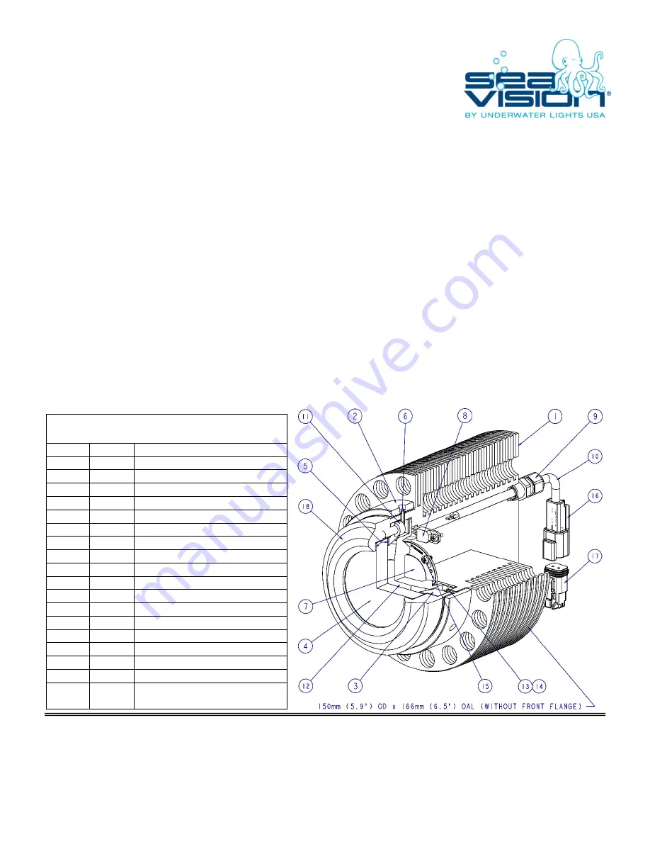
Installation:
This light should be installed at minimum 250-300mm (10-12”) below the light load water line with approximately a 20° down angle
by qualified/approved personnel using proper tools, welding procedures and materials. An access area of at least 75mm (3”)
should be left behind the light for servicing and general ventilation.
After selecting a location, cut an appropriate sized hole through the vessel hull. Note: Hole size will be defined by the specific weld-
in Front Flange (18) that came with the light. Caution! Check that no electrical wiring, fuel lines, oil lines, water lines etc., pass
near or through the intended hole location. Note: In order to allow proper heat dissipation from the installed lights it is important
to ensure that any hull insulation/cladding is not in contact with the thru hull or light body. It is recommended that a minimum of
30mm (1.2”) of clear space should be surrounding the fixture to allow for adequate cooling.
Place the supplied Front Flange (18) into said hole and following common ship building practices, permanently weld-in place. Note:
Leave the factory installed block-off disk and protective cap on the supplied Front Flange (18) until final light assembly.
Final light assembly - Remove Front Flange (18) block-off disk, protective cap and clean all surfaces. Install two Glass Gaskets (5)
(one gasket on either side of glass) Glass (4), Glass Retaining Ring (3) and six fasteners (13) tightened in a criss-cross pattern to 9
Nm (7 ft/lbs) using a 5mm allen wrench. Screw Connecting Ring (2) with attached Main Body (1) onto Front Flange (18) and
tighten to 40 Nm (30 ft/lbs). Note: Apply anti-seize compound to Connecting Ring (2) threads. Upon making proper electrical
connections (see driver box manual), connect Receptacle (16) to plug (17). Note: Upon completing light installation, it is highly
recommended that the Front Flange (18) be coated with antifouling paint.
Serviceable Parts:
This light is fully serviceable and all parts are replaceable. Please contact our technical support staff to discuss your individual
needs.
For Glass (4) replacement, disconnect Receptacle (16) from Plug (17), remove Connecting Ring (2) with attached Main Body (1),
remove six fasteners (13), Glass Retaining Ring (3) and Glass Gaskets (5). Upon thoroughly cleaning all surfaces, reverse said
procedure to assemble the new Glass (4) and Glass Gaskets (5). Note: Tighten all six fasteners (13) in a criss-cross pattern to 9
Nm (7 ft/lbs) using a 5mm allen wrench.
Caution! Never attempt to remove/replace Glass (4) while vessel is in the
water.
MODELS B15_12A41-12G32L, 120/230VAC (STEEL)
MODELS B15_10A41-12G32L, 120/230VAC (ALUMINUM)
BALLOON
PART
DESCRIPTION
1
14323
MAIN BODY / COFFERDAM
2
14002
CONNECTING RING
3
14004
GLASS RETAINING RING
4
14007
GLASS
5
14008
GLASS GASKET
6
14009
CONNECTING RING GASKET
7
14310
LED ARRAY
8
14321
THERMOSWITCH
9
14305
CABLE STRAIN RELIEF
10
14306
ELECTRICAL CABLE
11
14015
M6 x 1.0 x 14LG SST SHCS
12
14320
SILICONE LENS
13
14319
LENSE HOLDER
14
14322
M7 x 0.7 x 8LG SST PPHS
15
14307
M3 x 0.5 x 5LG SST PPHS
16
14316
RECEPTACLE ASSEMBLY, 2-WAY
17
14317
PLUG ASSEMBLY, 2-WAY
18
N/A
CALL TECHNICAL SUPPORT FOR
APPROPRIATE FRONT FLANGE
SV14 LED Light
Underwater Lights USA, LLC
Underwater Lights Europe Sarl
3406 S.W. 26
th
Terrace, C 6/7
16, rue Rouaze
Fort Lauderdale, FL 33312 USA
06400 Cannes, France
Phone: 1-954-760-4447
Phone: 33-(0)-4-97-21-02-96
Fax: 1-954-525-3261
Fax: 33-(0)-4-97-21-10-96
Internet: www.seavision.com
Internet: www.seavision.com
Email: [email protected]
DOC:022412-4
Email: [email protected]
STEEL/ALUMINUM


