UMAX Data Systems Astra 1220U Скачать руководство пользователя страница 6

Service Manual 


Scanner Settings 


Scaling: ............................................. 

1% to 200% in 1% increments at 600 dpi Resolution 

Highlight/Shadow: ........................... 

255 steps 

Brightness: ....................................... 

-100% ~ 100% 

Gamma Curve: ................................. 

Downloadable Curves 

Data Output 


Color Mode: ...................................... 

30 Bits (Hardware) 36 Bits (System) 

Grayscale Mode: .............................. 

10 Bits (Hardware) 12 Bits (System) 

Interface: .................................................. 

USB 

Power Requirements 


Voltage: ............................................. 

DC12 V (AC) 

Power Consumption: .............................. 

Maximum 12 Watts 

Environmental Ranges 


Operating Temperature: .................. 

10°


C ~ 35° C 

Relative Humidity: ........................... 

10% ~ 85% 

Dimensions: ............................................. 

471mm x 312mm x 98mm 

Net Weight: ............................................... 

3.65 Kg 

Systems Supported: 

PC  


*Product Specifications subject to change without notice. 

 2 

Содержание Astra 1220U

Страница 1: ...Astra 1220U Color Scanner Service Manual UMAX Data Systems Inc 0898 e...

Страница 2: ...wer to the scanner or its components If and when the scanner must be connected to a power source while maintenance or testing is performed use extreme caution when working on scanner electronic compon...

Страница 3: ...Component Assembly Overview 16 Component Replacement Kits 16 Astra 1220U Main Components 21 4 Troubleshooting Guide 28 Maintenance Notice 28 Cleaning and Repair Suggestions 28 5 Environment vs Perform...

Страница 4: ...Pin Assignment 44 iv...

Страница 5: ...ts This service manual is provided so that qualified maintenance and repair technicians can perform service as needed Scanner Specifications Scanner Type Flatbed Preview Speed 31 6 seconds A4 size Col...

Страница 6: ...or Mode 30 Bits Hardware 36 Bits System Grayscale Mode 10 Bits Hardware 12 Bits System Interface USB Power Requirements Voltage DC12 V AC Power Consumption Maximum 12 Watts Environmental Ranges Operat...

Страница 7: ...o focus the reflected light from the surface of the document onto a Charged Coupled Device CCD A mechanical system that uses a stepping motor attached to a gear assembly The gear assembly drives a tim...

Страница 8: ...to focus and reduce the size of the image Resolution of Lens is 600dpi A support chassis for the mounting of mirrors lens mount and CCD A stepping motor gear train and timing belt to move the optical...

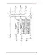
Страница 9: ...D_N RA0_8 RD0_7 NS_RS NS_PH1 NS_PH2 128 256K A B A B U_HOME DETECT U_A B A B MCLK J1 J2 J3 J4 J7 M B System Block Diagram 7805 5V 12V R1 R2 TGI SEL1 SEL2 U2 U4 Q4 U5 ASTRA 1220P ASIC S_CTR1_3 S_STATUS...

Страница 10: ...ng Diagram Pixel The following diagram shows the Video test pin signal during a scan while in color mode VIDEO Test Timing Diagram Line The following diagram shows the VIDEO test timing diagram during...

Страница 11: ...Service Manual CCD Test Timing The following diagram a provides a reference timing pattern for the CCD 3 5V 7 5V B G R 7...

Страница 12: ...Service Manual Component Connectors The following series of circuit diagrams show connections for the various electronic components ASIC Pin Assignment 8...

Страница 13: ...Service Manual DRAM and UTA Connector Pin Assignment The following diagrams give detailed information for the PC and the printer interface pins 9...

Страница 14: ...Service Manual AD Pin Assignment 10...

Страница 15: ...Service Manual Motor and To CCD Board Pin Assignment 11...

Страница 16: ...Service Manual Power Code Pin Assignment 12...

Страница 17: ...Service Manual EPP to USB Bridge Pin Assignment 13...

Страница 18: ...Service Manual CCD Pin Assignment OS3 SS RS CP SS NC NC 02 01 SH3 SS OS2 OS1 OD SP NC SS NC 02 01 SH1 SH2 1 2 3 4 5 6 7 8 9 10 11 22 21 20 19 18 17 16 15 14 13 12 PIN CONNECTIONS 2556D 14...

Страница 19: ...Service Manual 3797P 15...

Страница 20: ...ordering replacement kits be sure to include associated part numbers with your purchase order s Astra 1220U Replacement Kits For Astra 1220Umodel scanners only Part No Description 030028 01 KIT M B P...

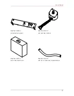
Страница 21: ...Service Manual Part No 030028 01 Part No 030032 13 KIT M B PLATE 1220U KIT MOTOR 35DX16T Part No 030072 55 Part No 030104 23 KIT CARTON KTX TAU KIT FLAT CABLE 24P NO SHIELDING 17...

Страница 22: ...08 Part No 030202 16 KIT DOCUMENT COVER Astra 1220 KIT UP HOUSING Astra 1220 Part No 030203 09 Part No 030205 05 KIT MOTOR A SSY 35Dx16T W O CORE KIT INV 2 6 px250x1 S12III Garear Part No 030206 10 K...

Страница 23: ...No 030519 13 KIT SPS 100 240V 12VDC UK PLUG CORE KIT SPS 100 240V 12VDC ASTRL PLUG CORE Part No 030519 14 Part No 030519 15 KIT SPS 100 240V 12VDC USA PLUG CORE KIT SPS 200 240V 12Vdc 1A EUR PLUGIN P...

Страница 24: ...Service Manual Part No 030742 00 Part No 030743 01 KIT WIRE LED Astra 1220P KIT PCBA M B 1220U Part No 030788 00 KIT CABLE USB A TOB 1 5M CORE 20...

Страница 25: ...tions in the table below Diagrams of main components and associated part information tables are included in the pages that follow Scanner Component Exploded Diagram ITEM Description 01 MECH PARTS SUNR...

Страница 26: ...Service Manual Document Cover Assembly ITEM Description 01 COVER DOCUMENT SUNRISE 02 SPONGE 296X218 LIFE 03 SHEET PVC 299X221 CWT LIFE 04 HINGE COVER SUNRISE 22...

Страница 27: ...Service Manual Upper Housing Assembly ITEM Description 01 UP HOUSING SUNRISE UCC017 02 RETAINER SUNRISE UCC017 03 SHEET CALIBRATION SUNRISE 04 GLASS WINDOW SUNRISE 05 TAPE 18MM 06 TAPE 12MM 23...

Страница 28: ...SUNRISE 02 SPRING PULLEY MOUNT LIFE 03 ROD 10D LIFE 04 05 RUBBER TIMING BELT 380T LIFE 06 DOWN HOUSING SUNRISE 07 M ASSY IDLER PULLEY SUNRISE 08 M ASSY MOTOR SUNRISE 09 PCBA H890 USE M B SUNRISE 10 PL...

Страница 29: ...01 MOUNT IDLER PULLEY SUNRISE 02 E RING 5D NI 03 PULLEY IDLER 25T C P2 032 Motor Frame Assembly ITEM Description 01 MOTOR MITSUMI M35SP 7 02 MOTOR MOUNT SUNRISE 03 E RING 5D NI 04 SCREW MCT T M3 X 6...

Страница 30: ...Service Manual Lamp Assembly ITEM Description 01 LAMP A SSY D2 6X250 02 SHEET REFLECTOR SUNRISE 03 HOLDER LAMP LIFE 26...

Страница 31: ...6X250X1 S12III BTC 04 SCREW MCP M3X5 BLK 05 CLIP MIRROR W7X6MM 06 CLIP MIROR W9X11MM 07 M ASSY LAMP ASTRA 1220P 08 RING CIRCULAR 4D EXT 09 MIRROR 80X12X3 10 ROLLER VX6 11 CHASSIS SUNRISE 12 LENS OD16...

Страница 32: ...f detergent which may penetrate the seams around the object glass and damage electronic components lens or mirrors inside Avoid the use of any corrosive detergent on the glass or housing Chassis When...

Страница 33: ...ransfer Function MTF of the optical system The following information might be useful in correcting a problem caused by misalignment Make sure all the screws on the optical assembly are tight and all o...

Страница 34: ...rious danger When disassembling the scanner be sure you never touch ICs especially the CCD without proper static protection Dust If a scanner is used in a dusty environment such as a factory dust coul...

Страница 35: ...17 C19 C22 C24 AGND J3 ULN2003 9801CCV R23 C27 B14 C28 Q2 R20 C23 C15 C16 C18 R18 C21 R22 C26 C14 R16 C20 TP3 L1 Q1 R17 C B E B10 93C46 PM8630 U6 B11 B12 B8 B9 C25 B16 B24 C33 X2 256KX8 B7 R14 B6 RP1...

Страница 36: ...SE CCD B 17 16 32 C2R3 Q1 R4 R5 R28 1 Q5 R13 R10 R9 R12 R29 B2 R24 R11 Q2 C7 R27 L2 C14 C9 C12 C13 U3 U2 R8 B1 C10C8C15 C11R25R26 Q3 Q4 R6 R7 C4 C1 R2 R1 C5 C6 L1 23 24 1 2 SILKSCREEN TOP SIDE CCD Boa...

Страница 37: ...Service Manual Appendix B Scanner Outline Diagram 312 83 98 471 33...

Страница 38: ...r s Replacement Kits Part No Description 030032 14 KIT MOTOR 12V M42SP 4 SUN 030072 47 KIT CARTON UTA 3A 030088 21 KIT LAMP A SSY COLD CATHODE UTA 3A 030104 25 KIT FLAT CABLE UL2896 8P 420mm SUN 03011...

Страница 39: ...030072 47 KIT MOTOR 12V M42SP 4 SUN KIT CARTON UTA 3A Part No 030088 21 Part No 030104 25 KIT LAMP A SSY COLD CATHODE UTA 3A KIT FLAT CABLE UL2896 8P 420mm SUN Part No 030113 08 Part No 030146 04 KIT...

Страница 40: ...t No 030203 08 KIT UP HOUSING UTA 3A KIT MOTOR A SSY 12V M42SP 4 Part No 030205 06 Part No 030212 01 KIT INV 9V 2 6 x250x1 Sun COTEK KIT HINGE A SSY UTA 3A Part No 030690 00 Part No 030691 00 KIT PCBA...

Страница 41: ...am along with part number descriptions in the table below Diagrams of main components and associated part information tables are included in the pages that follow Main Parts Assembly Diagram ITEM Desc...

Страница 42: ...l Housing Assembly Diagram ITEM Description 01 PLATE WINDOW 02 HINGE A SSY SUN 03 SCREW TCT A 4DX7 NI 04 SCREW TCT A 3DX7 NI 05 HOUSING SUN UCCXXX 06 PANEL LOGO UTA 3A 07 PAD PVC 21 5X6 UTA V 08 TAPE...

Страница 43: ...01 CABLE 9P 230MM UTA JADE II CORE 02 FLAT CABLE UC2896 8P 420MM SUN 03 SPRING OD14XL16X 1 0 04 COVER BOTTON USN UCCXXX 05 SCREW TCP PB 3DX7 NI 06 SCREW TCT A 4DX7 NI 07 SCREW MCP M3X5X16 D4 0 NI 08 S...

Страница 44: ...bly Diagram ITEM Description 01 INV 9V 2 6 X250X1 SUN COTEK 02 HOLDER LAMP SUN 03 CAP LEFT LAMP SUN 04 CAP RIGHT LAMP SUN 05 SHEET DIFFUSE 240X16 2MM SUN 06 SHEET REFLECT 264X23MM SUN 07 LAMP A SSY D2...

Страница 45: ...SUN 03 BLOCK POSITIONING UTA V 04 SHAFT ROD SUN 05 BRACKET MOTOR SUN 06 SCREW MCT T M3X6 NI 07 SCREW MCP M3X12 ZN 08 SCREW MCP T M4X6M ZN 09 E RING 2 5D NI 10 E RING 5D NI 11 RUBBER TIMER BELT 397T S...

Страница 46: ...01 SHAFT HING D5 9X34 1 02 SPRING HINGE UTA V 03 FRAME HINGE UTA V 04 HINGE BASE SUN 05 E RING 5D NI 06 BLOCK FRICTION UTA V PART2 07 BLOCK FRICTION UTA V PART1 08 PAD HINGE UTA V 09 SHAFT HINGE D9X3...

Страница 47: ...Service Manual Main Components and Outline Diagram J2 1 8 D1 R7 R1 R2 C1 R8 C5 C4 C3 C2 J1 R6 U1 C6 B1 C2 J3 1 9 R3 R4 R5 Q1 E C A K P NO 510350 07 PCB H8H0 UTA 3A REV D 9829 Silkscreen Top 43...

Страница 48: ...Service Manual Pin Assignment 44...

Отзывы: