YO99-0874-DI-002-18
30
4.2 Operation
4.2.1 Exhaust start
(1) Flow the Cooling water.
(2) Close the main valve of the Mechanical booster pump and start running the Supplementary
pump to exhaust inside pipes.
(3) Start the operation upon the vacuum container was exhausted to the pressure lower than the
maximum suction pressure of the Mechanical booster pump.
(4) Start the mechanical booster pump when the vacuum chamber is pumped to below the maximum
intake pressure of the mechanical booster pump.
4.2.2 Exhaust stop
(1) Close the main valve of the Mechanical booster pump and stop it.
(2) The Mechanical booster pump shall keep running a while by the Rotor inertia. Check and ensure
that the rotation stopped through the Oil level gauge to stop the Supplementary pump.
(3) Open the Suction leak valve upon stopped the Supplementary pump to make atmospheric
pressure inside the Mechanical booster pump and Supplementary pump.
(4) Wait until the Pump cools down as far as you can touch by hand to stop flowing the Cooling
water.
(5) Discharge the water in the Pump unit and Cooling water piping in case where the environment
temperature comes down below 5
℃
under the state that the operation is stopped (Supply the
compressed air of 0.3MPaG (gauge pressure) through the Cooling water inlet without closing the
outlet.). Residual water, if any, might freeze up and cause crack of the Pump unit and/or Cooling
water pipe.
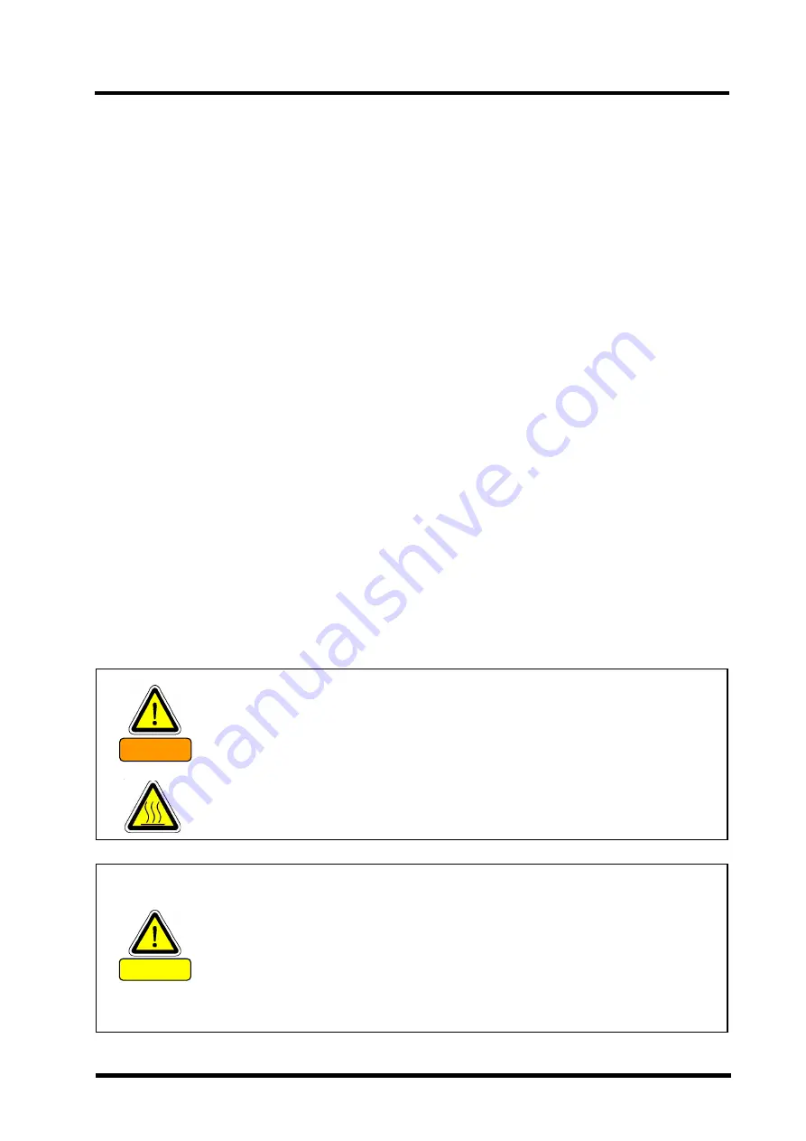
Be sure to close the Vacuum valve and stop the Pump operation to open the
Leak valve. Failure to follow this operation might cause the oil invasion in the
casing from the Lubrication chamber or otherwise give damage to the Pump.
Further the oil might flow back to the Vacuum tank if used the Oil rotation
pump as the Supplementary pump.
If failed in closing the Vacuum valve, the vacuum might leak from the Exhaust
system through the Pump.
CAUTION
The vacuum pump becomes high temperature during operation (70
℃
to 80
℃
).
Do not touch the Motor and/or Pump unit until the Pump cools down after
having stopped operation. Apply an appropriate protection to avoid to touch
the surface as necessary.
However, if the environment was highly humid, keep the Mechanical booster
pump warmer than the room temperature after having stopped it and make the
atmospheric pressure inside the Pump. Water in the air might condense in the
Pump and worsen the ultimate pressure and/or exhaust speed.
WARNING
Содержание PRC-003A
Страница 10: ...YO99 0874 DI 002 18 ix Fig 1 Warning Label PRC 003A PRC 006A PRC 012A PRC 018A...
Страница 24: ...YO99 0874 DI 002 18 8 2 4 Dimensional drawing Fig 3 PRC 003A Dimensional drawing...
Страница 25: ...YO99 0874 DI 002 18 9 Fig 4 PRC 006A Dimensional drawing...
Страница 26: ...YO99 0874 DI 002 18 10 Fig 5 PRC 012A Dimensional drawing...
Страница 27: ...YO99 0874 DI 002 18 11 Fig 6 PRC 018A Dimensional drawing...
Страница 56: ...YO99 0874 DI 002 18 40 5 6 Optional attachment figure Fig 14 PRC 003A Optional attachment figure...
Страница 57: ...YO99 0874 DI 002 18 41 Fig 15 PRC 006A Optional attachment figure...
Страница 58: ...YO99 0874 DI 002 18 42 Fig 16 PRC 012A Optional attachment figure...
Страница 59: ...YO99 0874 DI 002 18 43 Fig 17 PRC 018A Optional attachment figure...
Страница 76: ......


