background image

5. The most common setup process for welding applications:

1. Connect the transducer (tran amp mould combination) through the 2-core aviation

plug on the back of the device.

2. Connect the equipment to 220VAC power and turn on the power.

3. On the touch screen interface, click the "Frequency Search" button to enter the frequency search

interface, and press the "Start" button to search the resonance frequency of the welding head.

4. After successful search, it will automatically exit to the main interface. If an error is reported,

please check the possible cause according to the instruction manual.

5. Set the amplitude to 40%. According to the sonic test, observe whether the current is within 1A,

whether the power is within 500W, and whether the sound is mainly based on crisp model

frequency sounds. If you report an error that is out of range, you should check the mold or

transducer for abnormalities, and the mold is not tightened, cracked, etc.

6. Short the pins 1 and 6 of the DB9 interface on the back of the device through a control device

such as a button or PLC. Start ultrasound

7. Adjust the amplitude according to the welding result to meet the welding requirements. Note that

after adjusting the amplitude, the sound wave needs to be restarted to take effect.

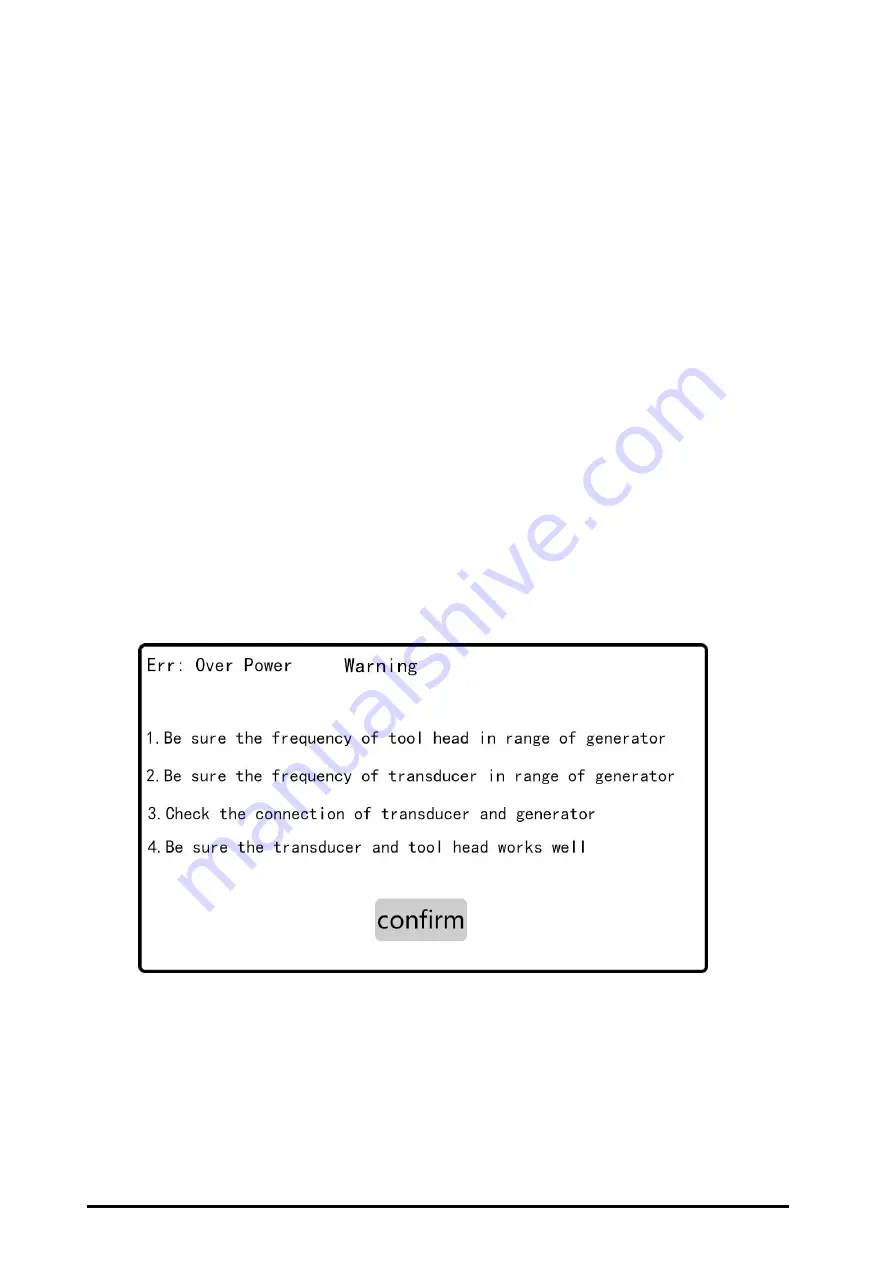
6. Warning messages and possible causes

6.1 Error: Lock frequency is out of DAC coarse adjustment range

Triggering this protection indicates that the frequency has lost lock, and the microcontroller

frequency is adjusted to its own capacity limit or the correct operating frequency has not been

found.
When this error occurs, try:

Содержание JYD-2700S

Страница 1: ...anual I Basic information introduction II Environment Requirements III Connecting ports introduction IV Display interface and parameter introduction V The most common setup process for welding applica...

Страница 2: ...ght 7KG Color light grey Features Automatic frequency tracking The system automatically tracks the resonance frequency of the welding head Compensate for detuning caused by heat and other reasons Digi...

Страница 3: ...ature 25 C to 70 C Relative temperature 30 to 90 without condensation warning To ensure that the ultrasonic generator has good ventilation care must be taken not to cover the generator s ventilation o...

Страница 4: ...7 8 can share a line Attention The power plug must be inserted into a socket with a ground terminal The adaptable power supply range of the ultrasonic signal generator is 220VAC 10 50 60Hz By adjusti...

Страница 5: ...utput power of the whole machine Production Used to record production yield Only the number of times the entire welding process has been performed is recorded Emergency stops during the welding proces...

Страница 6: ...whether the power is within 500W and whether the sound is mainly based on crisp model frequency sounds If you report an error that is out of range you should check the mold or transducer for abnormal...

Страница 7: ...the horn with a ratio of 1 2 or less This is what we recommend The traditional 1 3 horn is more suitable for traditional self excitation ultrasound Re search the resonance frequency and set the freque...

Страница 8: ...ls and perform frequency search Check if the mold is damaged Disassemble the mold or replace it with a mold that is confirmed to be good and check again Whether the load is short circuited Check wheth...

Страница 9: ...or 24V 5V 3V3 etc The system detects that the core voltage is not within the set range When this prompt occurs try Contact us If you still cannot find the cause after above testings please contact us...

Отзывы: