POWER ASSISTED STEERING SYSTEM
-
page 29
of 143
Installation, Maintenance and Owner's Manual
ULTRAFLEX
E
N
G
L
ISH
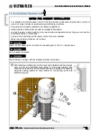
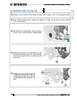
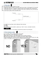
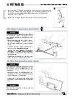
2 Fix the power unit to the wall or to the floor by using
the four self-tapping screws (7) and washers (8) with
a proper torque according to the support type, without
exceeding 8 Nm (5,9 lb ft).
7
8
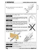
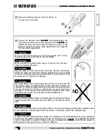
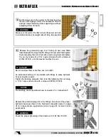
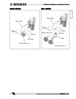
3 Remove the protection plugs. Put T fitting (9) near side TANK
(identified with T) and put the 90° fitting (10) near side P and tighten
them manually; then turn them after unscrewing them and tighten
the nut by means of a 11/16" open end wrench with a torque of
20 Nm (15 lb ft) until the washer touches the unit.
9
WARNING
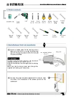
Make sure the wall or the floor where the power unit will
be installed can bear its weight (about 12 Kg, 26.4 pounds)
DANGER
Do not unscrew them more than one turn (360°).
1 0
1 1
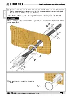
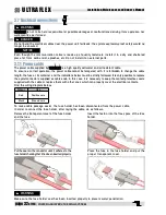
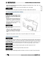
An extension bushing (11) is provided with fittings to make hydraulic
hose connection easier.
Tighten the bushing manually, then lock it by tightening the nut using
a 11/16" open end wrench with a torque of 20 Nm (15 lb ft).
NOTICE
The bushing can be positioned near connection T or connection P.
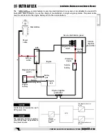
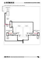
Remove the protection plugs from the fittings, then connect the proper
hydraulic hoses as shown in the "Hydraulic connection layout" on page
18 for single station applications and on page 20 for dual station
applications.
WARNING
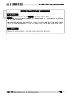
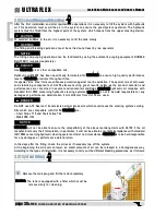
Check the proper tightening of the bleed nut (12) 20 Nm (15 lb ft).
1 2

