background image

POWER ASSISTED STEERING

SYSTEM

ULTRAFLEX

PARTNER

Installation,  maintenance and owner's  manual

R

IT

A

L

IA

NO

E

N

G

L

ISH

IT

A

L

IA

NO

F

R

A

N

Ç

A

IS

(

dr./dis./des. n°

 28117/f 17/12/2014)

(COD. 74204K - REV 06)

Содержание MasterDrive

Страница 1: ...POWER ASSISTED STEERING SYSTEM ULTRAFLEX PARTNER Installation maintenanceandowner s manual R IT A L IA N O E N G L IS H IT A L IA N O F R A N Ç A IS dr dis des n 28117 f 17 12 2014 COD 74204K REV 06 ...

Страница 2: ... the customer maintain and improve the quality standards constantly pursue a continuous process improvement to meet the market needs and to increase the customer satisfaction ULTRAFLEX Environmental Management System is certified CISQ IQNet by the Italian Shipping Registry RINA in conformity with the UNI EN ISO 14001 rule ULTRAFLEX certification No EMS 1282 S Products for pleasure boats are consta...

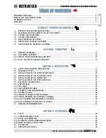
Страница 3: ...22 3 3 INSTALLATION OF THE FRONT MOUNT HELM 22 3 4 INSTALLATION OF THE TILT MOUNT HELM 26 3 5 INSTALLATION OF THE POWER UNIT 27 3 6 INSTALLATION OF THE USER INTERFACE 31 3 7 ELECTRICAL CONNECTIONS 32 3 7 1 POWER CABLE 32 3 7 2 KEY CABLE 36 3 7 3 USER INTERFACE CABLE 36 3 8 SYSTEM FILLING AND BLEEDING 38 3 8 1 SYSTEM FILLING 38 3 8 2 SINGLE CYLINDER SYSTEM BLEEDING 39 3 8 3 SINGLE STEERING STATION ...

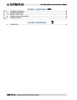
Страница 4: ...ge4of143 POWER ASSISTED STEERING SYSTEM E N G L IS H SECTION5 MAINTENANCE 5 1 ROUTINE MAINTENANCE 45 5 1 1 CLEANING OPERATIONS 45 5 1 2 ANNUAL INSPECTIONS 45 5 2 STEERING WHEEL DISASSEMBLY 45 5 3 TROUBLESHOOTING 46 SECTION6 DISMANTLING 6 1 DISMANTLING 47 ...

Страница 5: ...Revision description 0 1 2 3 4 5 6 10 02 2012 08 03 2013 25 06 2013 29 10 2013 17 07 2014 04 11 2014 17 12 2014 First edition Addition of automatic start Addition of Slave helm Addition of start customization Use with inboard cylinders has been added List modification of inboard cylinders Addition of 50cc helm Oil specification change ...

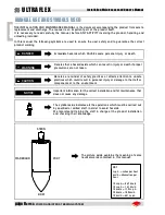
Страница 6: ...al LEGEND m p h miles per hour km h kilometres per hour 10 m p h 8 69 knots 10 m p h 16 1 km h 10 knots 11 5 m p h 10 knots 18 5 km h 10 km h 6 21 m p h KEY DANGER Immediate hazards which CAUSE severe personal injury or death WARNING CAUTION The symbol aside indicates all the operations which must be carried out by qualified or skilled staff in order to avoid hazards We recommend training the staf...

Страница 7: ...n integrant part of the product and should be easily available to staff in charge of use and maintenance The user must know the content of this manual ULTRAFLEX declines all responsibility for possible mistakes in this manual due to printing errors Although the main features of the type of product described are not subject to change ULTRAFLEX Company reserves the right to modify any parts details ...

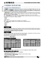
Страница 8: ... UC128 SVS UC116 I UC168 I UC215 I UC293 I The main features of the system are Three different selectable levels of power PATENTED High efficiency low Amp draw Immediate control in any sea conditions through the system always running Safety switch ON OFF SMART BUTTON Suitable for use with autopilot WARNING DANGER The 32cc helm 3 75 total steering wheel revolutions must be used with single UC 128 S...

Страница 9: ...stallation and maintenance manual 1 Steering wheel please refer to the corresponding section of the ULTRAFLEX catalogue 1 2 Warnings forthecorrect useof theproduct ULTRAFLEX steering systems must not be installed on race boats All ULTRAFLEX steering systems must not be installed on boats equipped with engines whose maximum horsepower is higher than the horsepower rating approved by boat manufactur...

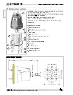
Страница 10: ...t Mount and Tilt Mount versions Tilt Mount version is suitable for use with X66 not supplied Built in relief valves Master Front version only 3 4 tapered shaft Master Front version only Corrosion resistant painted body Master Front version only Waterproof FRONT MOUNT VERSION 2 1 32cc 40cc 50cc Helm Shaftforsteeringwheelconnection Shaft seal Dashboard seal Spacer 4x not supplied for 50cc helms Fixi...

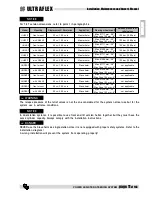
Страница 11: ...05 bar 1500 psi UH32 T with X66 tilt 32 cc 1 95 cu in Master helm Max Ø 508 mm 20 Max Cone 152 mm 6 105 bar 1500 psi UH40 F front mount 40 cc 2 44 cu in Master helm Max Ø 711 mm 28 Max Cone 152 mm 6 105 bar 1500 psi UH40 T with X66 tilt 40 cc 2 44 cu in Master helm Max Ø 508 mm 20 Max Cone 152 mm 6 105 bar 1500 psi UH50 F front mount 50 cc 3 05 cu in Master helm Max Ø 711 mm 28 Max Cone 152 mm 6 1...

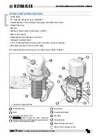
Страница 12: ...t Salt water resistant motor 4 5 m 15 Wiring Harness to key battery and user interface included Waterproof except for the vent filler plug 2 3 1 2 1 5 4 8 6 7 8 8 8 9 10 Power unit oil tank with filter Vented filler plug Motor Power control electronic unit WARNING Never remove the cover otherwise warranty willbe void and thesystem explosion proof safety will no longer be ensured 1 2 3 Key cable Fi...

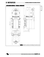
Страница 13: ...on MaintenanceandOwner sManual ULTRAFLEX E N G L IS H APPLICATION EXAMPLE OVERALL DIMENSIONS 203 mm 7 99 416 mm 16 38 110 mm 4 33 200 mm 7 87 130 mm 5 12 178 mm 7 01 198 mm 7 80 158 mm 6 22 NOTICE Consider the wiring harness and hydraulic hose dimensions ...

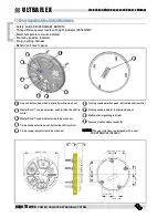
Страница 14: ... when in standby white when on MasterDrive mode selection push button backlit in white MasterDrive mode indicator led blue when on Cruise mode selection push button backlit in white Cruise mode indicator led blue when on 1 2 3 Fishing mode selection push button backlit in white Fishing mode indicator led blue when on Malfunction signalling led red Communication cable connector 6 7 8 4 5 9 3mm 0 12...

Страница 15: ...inglestationpackagingcontents n 1 power unit with cables n 4 silent blocks fixing brackets n 4 sealing washers for silent block fixing n 4 stainless steel washers for silent block fixing n 4 self locking nut for silent block fixing n 4 nut cap covers for silent block fixing n 4 self tapping screws for the power unit fixing to the wall and 4 stainless steel washers MD KIT FRONT MOUNT APPLICATION n ...

Страница 16: ...ts for fixing to the dashboard n 4 stainless steel washers n 1 seal MD KIT TILT APPLICATION n 1 helm with the same cylinder capacity as the Master helm UHD32 T or UHD40 T or UHD50 T according to the Master helm n 1 litre of hydraulic oil OL 150 ULTRAFLEX n 1 Slave helm communication cable n 1 straight fitting n 2 T fitting ORDER SEPARATELY n 1 OB MD kit whose length corresponds to the distance bet...

Страница 17: ...pressures up to 105 bar 1500 psi Do not disassemble or tamper with any assembled component Do not remove the electronic unit cover displaying the warning Don t open otherwise warranty will be void and the system explosion proof safety will no longer be ensured NEVER use the Slave helm as single station since it is not equipped with proper safety systems DANGER WARNING Do not put the feet on the cy...

Страница 18: ...ng and viceversa WARNING Check the correct connection of the Kit OB MD 8 between the helm and the power unit the hose coming from fitting T on the helm must be connected to fitting T on thepower unit and the hose comingfrom fitting P on the helm must be connected to fitting P on the power unit WARNING Since the section between the helm and the cylinder may be subject to pressure up to 105 bar 1500...

Страница 19: ...TARBOARD side Helm 4 R Fitting to connect the helm and the cylinder on PORT side Helm 5 T Fitting to connect the oil return hose from the helm Power unit 6 P Fitting to connect the high pressure hose to the helm Power unit 7 Kit OB SVS to connect the helm and the cylinder s grey Kit OB SVS 8 Kit OB MD MD to connect the helm and the power unit black Kit OB MD 9 STARBOARD side fitting for connection...

Страница 20: ...e system with single station is present drain all the oil out of the system without dispersing it into the sea NOTICE It is advisable to replace the existing oil with new oil and to dispose of the used oil in accordance with the regulations in force NOTICE The Slave helm is identified by a PVC disc to be removed during installation only NOTICE In case of use with inboard cylinders follow the indic...

Страница 21: ...o connect the Slave helm and the cylinder PORT side Slave helm 9 T Fitting to connect the oil return hose from the helm Power unit 10 P Fitting to connect the high pressure hose to the helm Power unit 11 OB MD kit for connection between power unit P and straight fitting black and between Master helm T and power unit T black Kit OB MD 12 Straight fitting Slave helm kit 13 OB MD kit for connection b...

Страница 22: ...ts pipes and fittings In order to fix the helm properly the maximum dashboard thickness must be 25 mm 1 Different thicknesses could compromise the driving safety Make sure that the fixing screws pass through the supplied self locking nuts completely WARNING Torque wrench Drill Open end wrench 10 mm Open end wrench 11 16 Open end wrench 7mm MOLYKOTE 1000 Screwdriver Allen wrench 5mm Open end wrench...

Страница 23: ...re that pipes are perfectly clean and free from swarf If copper or steel pipes are used cleaning is mandatory If the installer uses pipes that are different from those indicated in this manual he must take full responsibility for it WARNING WARNING Keep the pipes far from heat sources and from chemical substances Protect the pipes that must pass through bulkheads by using suitable thru hulls The b...

Страница 24: ...ard by means of screws 3 nuts 4 and washers 5 after positioning flange 6 in the rear part of the dashboard and flange 7 with spacers 8 in the front part of it not supplied for 50cc helms Tighten the four self locking nuts 4 by using a 10 mm wrench with a torque of 10 Nm 7 37 lb ft If the self locking nuts 4 are disassembled they must be replaced Contact our Technical Assistance Service see page 7 ...

Страница 25: ...operly fixed inside its seat 13 12 NOTICE Make sure hole 11 is positioned downwards so that condensation can be drained 10 8 Position the steering wheel supplied separately 14 on the helm shaft 15 by using the suitable key 16 Insert washer 17 and tighten the self locking nut 18 with a 15 16 open end wrench and with a torque of 40 Nm 29 5 lb ft then grease the thread by using some anti seize grease...

Страница 26: ...l and for the helm and its pipes and fittings 1 2 12 12 12 min 510 mm 20 08 in Tilt X66 is supplied separately CAUTION 2 2 Fix bracket 1 supplied with tilt X66 to dashboard 2 following the instructions supplied with tilt X66 1 3 Fix the helm to bracket 1 supplied with tilt X66 by using the three M6 screws 3 supplied with tilt X66 following the instructions provided with tilt X66 1 3 4 Position mec...

Страница 27: ...p clean Make sure that working areas are free from dust and dirt The protective plugs of threaded holes must be removed only before the connection of fittings and pipes Make sure that pipes are perfectly clean and free from swarf If copper or steel pipes are used cleaning is mandatory If the installer uses pipes that are different from those indicated in this manual he must take full responsibilit...

Страница 28: ...hich can bear the weight of the product In order to ensure a correct working in any sea condition and operation mode the power unit must be mounted vertically or horizontally In case of floor mounting put the power unit far from water puddles Make sure electrical cables are not crushed 1 After selecting a suitable place for the power unit installation see the previous note turn the four silent blo...

Страница 29: ...her touches the unit 9 WARNING Make sure the wall or the floor where the power unit will be installed can bear its weight about 12 Kg 26 4 pounds DANGER Do not unscrew them more than one turn 360 10 11 An extension bushing 11 is provided with fittings to make hydraulic hose connection easier Tighten the bushing manually then lock it by tightening the nut using a 11 16 open end wrench with a torque...

Страница 30: ...Center ULTRAFLEX declines any responsability about the compatibility and the correct operation of the system after installing an autopilot After checking compatibility remove vent from T fitting 9 by unscrewing nut 12 see previous page Connect the compensation pipe coming from the autopilot to the 9 16 24 UNEF thread on the fitting NOTICE The autopilot must be placed at a lower height with respect...

Страница 31: ...1 Position the user interface so that it does not hinder other controls or that it is not hindered by them 2 Refer to the overall dimensions indicated in paragraph 1 7 to make sure the interface can be installed in the chosen position 3 After choosing the right position make the holes to insert the user interface with the suitable template 5 Position the user interface 2 and fix it to dashboard 3 ...

Страница 32: ...erly cover the electrical contacts Find the wiring diagram below To make cable passage easier the fuse holder has been disconnected from the power cable In order to connect the fuse holder after laying the cable do as follows WARNING Make sure the fuse holder seal has been inserted properly to prevent water penetration DANGER Do not bend the electrical cables near the power unit fairleads the syst...

Страница 33: ...es in single engine systems the power cable must be connected to the engine battery and to the service battery NOTICE A 40A fuse is needed on each APS power line NOTICE The magneto thermal switches must be as close as possible to the power source Masterdrive Power cable APS Fuse on cable Magneto thermal switch Battery disconnecting device Engine battery Service distribution panel Engine negative g...

Страница 34: ...n engine system it must be connected to both batteries Masterdrive Power cable APS Fuse on cable Magneto thermal switch Battery disconnecting device Port engine battery Starboard engine battery Magneto thermal switch Battery disconnecting device Engine Engine Negative pole Positive pole Negative pole Positive pole ...

Страница 35: ...tteries solar cells etc The ground wire must be directly connected to the engine negative ground bar NOTICE It is possible that the negative ground bar is not used on the boat In this case the ground of the power cable should be located on the ground common point near the battery disconnecting devices WARNING Masterdrive Power cable Fuse on cable Battery disconnecting device Engine battery Engine ...

Страница 36: ...use diodes with the following minimum features Id 200mA Vbr 32 VDC Key connectors must be connected in a proper way in order to ensure a waterproof connection The user interface cable is supplied ready to be connected Make sure you hear a click confirming the connection Slightly pull the connector to check that connection has been properly performed Make sure the user interface cable is not stretc...

Страница 37: ...age37of143 Installation MaintenanceandOwner sManual ULTRAFLEX E N G L IS H Cover cable Cover cable Y cable Master helm cover Key cable Key cable Master helm cover Slave helm cover SINGLE STATION DUAL STATION Power supply Power supply ...

Страница 38: ...enhances protection against marine oxidation The special mix of anti wear and stabilizing components of OL150 allow ensuring great results as far as the product duration and performances are concerned in several environmental conditions ULTRAFLEX hydraulic oil complies with standard ISO 10592 concerning hydraulic steering systems ULTRAFLEX is not to be held responsible for any damages or performan...

Страница 39: ...p up the tank until reaching the maximum level When the system is off unscrew the two bleed valve protections and loosen nuts A of the two bleed valves 1 5 turns max Manually push the cylinder body to one side until it stops as shown in picture 1 Close the bleed valve on the cylinder end of stroke side with a torque of 20 Nm 15 lb ft and put an oil recovery tank near the other bleed valve as shown...

Страница 40: ...eding operations Follow the same bleeding procedure described for the single cylinder paragraph 3 8 2 While turning the steering wheel both cylinders move Repeat the entire procedure several times to be sure there is no air in the system 3 8 4Dualsteeringstation singlecylinder Manually unscrew the two bleed valves on the cylinder T fittings and push the cylinders to one side up to the end stroke P...

Страница 41: ...wheel rotation will be harder Repeat the procedure at least 3 times to ensure the absence of air in the system The purging procedure is the same for dual station dual engine single cylinder and tie bar NOTICE 3 8 5Dualsteeringstation dualcylinder Manually unscrew the two bleed valves on the cylinder T fittings and push the cylinders to one side up to the end stroke Position the oil bottle near the...

Страница 42: ...ady to be used NOTICE in such a condition the system is not enabled and battery consumption is about 200mA 3 Press the on push button 1 the system starts and goes to preset Cruise position and the relevant indicator 2 lights up The system is ready to be used NOTICE in such a condition the system is enabled and battery consumption is about 3A without turning the steering wheel 1 1 2 4 1 1 Preset Ma...

Страница 43: ...ystem confirms automatic mode is disabled by lighting all the indicators up five times Release push button 1 the system goes to stand by Press the on push button 1 to start the system 1 If automatic mode is selected after supplying the system with power engine key ON it is advisable to start engines immediately to avoid battery discharge WARNING 4 1 2Startcustomization It is possible to customize ...

Страница 44: ...dded together if they are carried out at the same time The controls on the panel work in parallel if an action is carried out on one station it is carried out on the other station too at the same time NOTE FOR DUAL STATION SYSTEMS WARNING ATTENZIONE It is possible to select three different power levels according to sailing conditions by pressing the relevant push buttons The indicator lights will ...

Страница 45: ...ions to keep the product in optimum operating condition thus avoiding that the external environment may jeopardize its operation and safety During boat seasonal maintenance and at the beginning of each season always check that electrical connections are clean and fastened securely WARNING 5 1 1Cleaningoperations Ordinary cleaning ensures good operation and optimum product aesthetics Only the helm ...

Страница 46: ...stem is stiff and hard to turn The system is very difficult to fill Air keeps bubbling at the top of the steering system tank even after filling the system completely Replace hoses Install hoses properly repeat the bleeding procedure of the system Tighten the bleeder on the cylinder Uncoil and straighten the hose Replace it if necessary DANGER The damaged hose must be replaced otherwise it may cau...

Страница 47: ...r any reason the steering system is put out of service it is necessary to follow some rules in order to respect the environment Sheaths pipelines plastic or non metallic components must be disassembled and disposed of separately The steering system CONTAINS POLLUTING OILS which must be disposed of according to the rules in force in the country ...

Страница 48: ...ULTRAFLEX S p A 16015 Casella Genova Italia Via Crose 2 ...

Отзывы: