background image

15

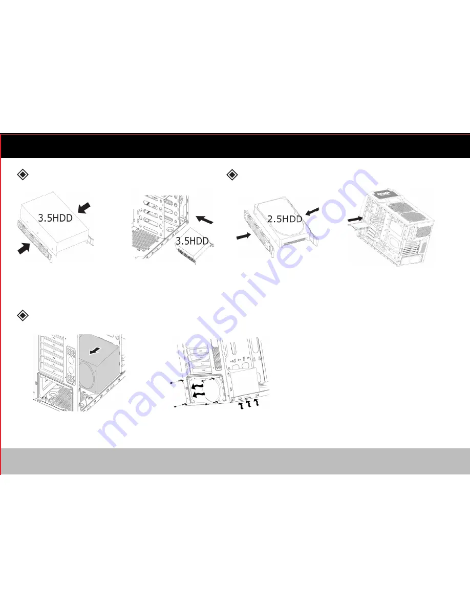
Power Supply Installation

3.5” Device Installation

2.5” Device Installation

Place the 3.5” tool-less clips onto the 

3.5” device in the proper location.

Place the power supply in the proper location.

Secure the power supply with screws.

Place the 2.5” tool-less clips onto the

2.5” device in the proper location.

Slide the 2.5” device into the drive 

bay from the right side of the case.

Slide the 3.5” device into 

the drive bay.

Содержание Defender II

Страница 1: ...User Manual MID TOWER GAMING CASE...

Страница 2: ......

Страница 3: ...Power Supply Installations Motherboard and Graphics Card Installations Avertissement Caract ristiques C bles Accessoires Installations de Dispositif 5 25 Installations de Dispositif 3 5 2 5 Installati...

Страница 4: ...nzene alcohol paint thinner mosquito repellent aromatics lubricant detergent etc Please wear gloves during the installation process to prevent injuries The power supply is sold separately Ensure the p...

Страница 5: ...k Coating inside Chassis or White White Coating Inside Chassis 520 L x 195 W x 476 H mm SGCC Steel ABS Mesh ATX Micro ATX 4 3 4 7 Slots Front 1 x 120mm LED Fans Rear 1 x 120mm Black Fan Top 2 x 120mm...

Страница 6: ...5 Cables Reset...

Страница 7: ...d off for M B Main Board Screws for Power Supply Screws for M B Stand off socket for M B Screws for Fans Screws for Securing Lockplate Lockplate for Anti Theft Straps for Cable Management Tool less Cl...

Страница 8: ...panel cover and pull to remove the cover Remove the screws securing the side panels Slide the side panel to remove it Pull the tool less drive bay clip Push the tool less drive bay clip to secure the...

Страница 9: ...to the 3 5 device in the proper location Place the power supply in the proper location Secure the power supply with screws Place the 2 5 tool less clips onto the 2 5 device in the proper location Slid...

Страница 10: ...hics card stabilizer Remove PCI slot brackets Adjust the graphics card stabilizer a When using slots 2 and 3 use the upper portion of the graphics card stabilizer b When using slots 3 and 4 use the bo...

Страница 11: ...ne benz ne alcool diluant peinture produit anti moustiques aromates lubrifiant d tergent etc S il vous pla t porter des gants pendant le processus d installation pour viter les blessures Source de Cou...

Страница 12: ...Coating inside Chassis or White White Coating Inside Chassis 520 L x 195 W x 476 H mm SGCC Steel ABS Mesh ATX Micro ATX 4 3 4 7 Slots Front 1 x 120mm LED Fans Rear 1 x 120mm Black Fan Top 2 x 120mm Fa...

Страница 13: ...Cables Reset 12...

Страница 14: ...off for M B Main Board Screws for Power Supply Screws for M B Stand off socket for M B Screws for Fans Screws for Securing Lockplate Lockplate for Anti Theft Straps for Cable Management Tool less Cli...

Страница 15: ...panel cover and pull to remove the cover Remove the screws securing the side panels Slide the side panel to remove it Pull the tool less drive bay clip Push the tool less drive bay clip to secure the...

Страница 16: ...nto the 3 5 device in the proper location Place the power supply in the proper location Secure the power supply with screws Place the 2 5 tool less clips onto the 2 5 device in the proper location Sli...

Страница 17: ...phics card stabilizer Remove PCI slot brackets Adjust the graphics card stabilizer a When using slots 2 and 3 use the upper portion of the graphics card stabilizer b When using slots 3 and 4 use the b...

Страница 18: ...2013 Streak Products Inc ULTRA is a registered trademark and ULTRA DEFENDER is a trademark of Streak Products Inc Streak Products is not responsible for typographical or photographic errors TECHNICAL...

Страница 19: ......

Страница 20: ......

Отзывы: