UIrobot UIM2501 Скачать руководство пользователя страница 6


Page


|


6


UIM2501

UI Robot Technology Co. LTD               M25020101008EN 

Network Operation 

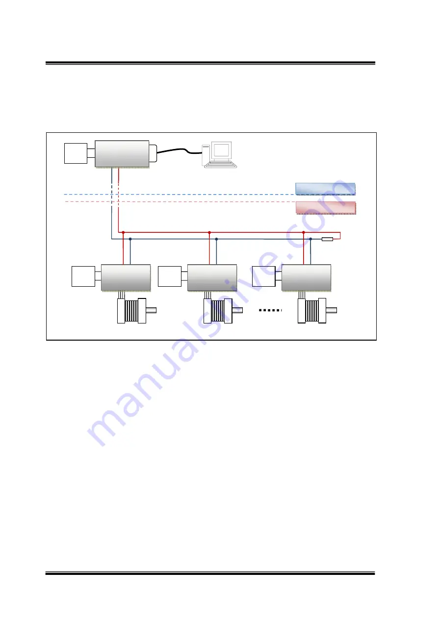
Multiple UIM242XX controllers can be wired together to form a reliable motor network. 
Following figure provides a typical network wiring solution.  

Figure 0-4: Wiring Scheme for Network Operation 


Notice: 

In multi-node CAN applications, it is important to maintain a direct point-to-point wiring 
scheme. A single pair of wires should connect each element of the CAN bus, and the two 
ends of the bus should be terminated with 120

 resistors. A star configuration should never 

be used.  

UIM2501 converter has a build-in terminal resistor. To enable the UIM2501 converter’s 
terminating resistor, please toggle the DIP8 to ON position. User only needs to attach a 
resistor at the UIM242 end of the bus. 

In addition, any deviation from the point-to-point wiring scheme creates a stub. The high-
speed edge of the CAN data on a stub can create reflections back down the bus. These 
reflections can cause data errors by eroding the noise margin of the system. Although stubs 
are unavoidable in a multi-node system, care should be taken to keep these stubs as small 
as possible.  


RS232

Motor


#1


6

40


VDC


Power


CANH


CANL

CANH

CANL


120


Ohm


C

ANH 

CA

NL


Factory


Control


Room


UIM250 

Controller 

12

40


VDC


Power


UIM242xx


Controller


1


Motor


#2

CANH


CANL


12

40


VDC


Power


UIM242xx


Controller


1

Motor


#100


CANH


CANL


12

40

VDC

Power

UIM242xx


Controller


1


Содержание UIM2501

Страница 1: ...RS23 32 CAN for U Us N2 0B UIM24 ser Conv 2XX M r Ma erting Motion anu UIM g Cont n Cont ual M2501 roller roller...

Страница 2: ...ur specifications UIROBOT MAKES NO REPRESENTATIONS OR WARRANTIES OF ANY KIND WHETHER EXPRESS OR IMPLIED WRITTEN OR ORAL STATUTORY OR OTHERWISE RELATED TO THE INFORMATION INCLUDING BUT NOT LIMITED TO I...

Страница 3: ...ption The UIM2501 RS232 CAN Converting Controller is used in conjunction with UIM242XX stepper motor controller to provide a RS232 interface on the user side and a CAN bus interface on the motor side...

Страница 4: ...DIP Switch UIM2501 controller has an 8 bit DIP switch which serves multiple functions When powering up DIP1 DIP7 are read as the UIM2501 controller s ID address After powering up DIP1 and DIP2 are as...

Страница 5: ...ion Notice For long distance transfer both ends of the bus should be terminated with120 terminating resistors UIM2501 converter already has a build in terminating resistor To enable it user needs togg...

Страница 6: ...resistor To enable the UIM2501 converter s terminating resistor please toggle the DIP8 to ON position User only needs to attach a resistor at the UIM242 end of the bus In addition any deviation from t...

Страница 7: ...Exposure to maximum rating conditions for extended periods may affect device reliability Electrical Characteristics Ambient Temperature 25 Supply Power Voltage 6V 40VDC Current Consumption Max 100mA C...

Страница 8: ...king Operation 12 3 1 Global Control Introduction 12 3 2 Controller ID Assignment Instruction SETADR 13 3 3 Object Specify Instruction ADR 13 3 4 Global Register Instruction gREG 14 3 5 Global Motor E...

Страница 9: ...n network with up to 100 UIM242XX controllers Interfacing the UIM2501 is simple intuitive and fault tolerating Users are not required to have stepper motor driving or CAN protocol knowledge UIM2501 su...

Страница 10: ...t 3 None Parity 2 2 Hand Shaking If user device knows the baud rate it can start sending instructions without hand shaking Hand shaking is more used as a method to check the existence and firmware ver...

Страница 11: ...e Message ID of instruction BDR The Reserved is for factory use Comment New Baud Rate will be stored in the controller s non volatile memory EEPROM New baud rate will take effect after the controller...

Страница 12: ...uction Besides the object specific operation UIM2501 can also send commands to all subsidiary UIM242XX controllers This process is called broadcasting or global control instruction 3 1 1 Global Instru...

Страница 13: ...tion of Set Address Every time there can be only one UIM242XX controller linked to the UIM2501 controller to get the ID assigned Once an ID is assigned the ID will be stored in the UIM242XX controller...

Страница 14: ...ted by the UIM2501 Controller the total number of all subsidiary UIM242xx controllers and their ID are recorded in the UIM2501 controller The returned QTY servers as an indicator of the health of the...

Страница 15: ...iable Integer x 0 1 ACK 0xAA QTY 0xAD 0xFF 3 9 Global Micro Stepping Resolution Setup Instruction gMCS Instruction gMCS Function Setup micro stepping resolution for all subsidiary UIM242 Controllers S...

Страница 16: ...up relative position control for all subsidiary UIM242 Controllers Syntax gSTP x Variable Integer x 0 1 2 000 000 000 ACK 0xAA QTY 0xAD 0xFF 3 13 Global Origin Point Setup Instruction gORG Instruction...

Страница 17: ...Page 17 UIM2501 Converting Controller M25020101008EN UI Robot Technology Co LTD Appendix A Dimensions mm Mounting 2 M3 depth 5...

Отзывы: