


Product Manual
Page 8 of 19
2022-10-31
4.3 Temperature Controller -Eurotherm 32h8
Reference should be made to the Eurotherm short-form Operating Manual
supplied with your unit on how to gain entry to each access level and basic
operation.
Full Operator Handbook can be downloaded from Eurotherm.co.uk or
Eurotherm.com.
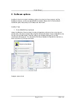
The ITools suite of programmes can be used for remote PC control via the
RS232 input. Refer to section 6 and the Eurotherm website.
Note: Always allow the Eurotherm
32h8 to complete its ‘start
-
up’
routine before operating any switches or digital inputs
4.4 Current meter/I Adjust
The front panel meter will display the current in the load from 00.0 to ~
Unit max Amps. When supplied as part of an order with a UHV Design in
vacuum heater the unit is normally current limited to just above the
maximum recommended this will be noted in the Test Data sheet.
The unit is current limited to ~ 27.0 Amps as factory default when
supplied as a free standing power supply.
4.5 Remote / Output Current & Voltage Monitor Signals
The rear panel 15-Way HD connector socket Remote functions are as
below:
Pin 1
Output I Sense +ve, 1mV/Amp
Pin 2
No Connection
Pin 3
LA, Link to Pin 8 to set Eurotherm 32h8 into ‘Standby’
(inhibit)
Pin 4
No Connection
Pin 5
Interlock: Link to Pin 15. Output will be inhibited until Pins 5
& 15 are linked
Pin 6
Output I Sense
–
ve
Pin 7
No Connection
Pin 8
C, Link to Pin 3 to set Eurotherm 32h8 into ‘Standby’
(Inhibit)
Pin 9
LC, Link to Pin 14 to select Second Setpoint on 32h8
Pin 10
No Connection
Pin 11
Output V Sense +ve, 1mV/Volt
Pin 12
Output V Sense -ve
Pin 13
Link to Pin 8 to set Eurotherm 32h8 into ‘Standby’ (inhibit)
mode when Output Switch is OFF
Pin 14
LB, See Pin 9
Pin 15
See Pin 5