


MD40
PRODUCT INSTRUCTION MANUAL
MD40
Page 22 of 56
Author: N.Carapiet | Revision: 1.1
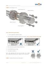
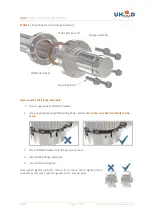
1.
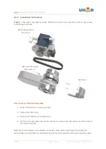
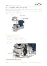
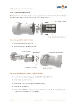
Loosen the 3 x M3 Grub Screws in the Adjuster Ring.
2.
Rotate the Adjuster Ring to the desired position.
3.
Re-tighten screws
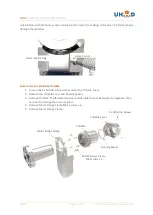
When finished making the necessary adjustments, replace the thimble cover and tighten the
grub screws.
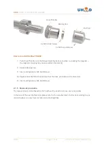
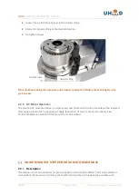
2.2.6 DC Motor Operation
To actuate a DC motorised drive, a simple speed and direction DC control module will be required.
All mating connectors are supplied to enable fabrication of custom connection cables. See
Technical Reference section of this manual for motor details.
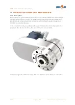
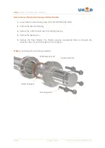
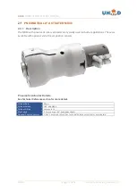
INLINE MOUNTED STEPPER OR DC MOTORISED MD40
2.3.1 Description
The stepper motor option allows for precise position control of the MD40. This can be selected
with optional home sensor or home sensor with limit switches. All options are available with
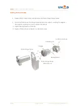
Grub Screws
Adjuster Ring
Содержание MD40 Series
Страница 41: ...MD40 PRODUCT INSTRUCTION MANUAL MD40 Page 41 of 56 Author N Carapiet Revision 1 1 3 1 3 Switch Pin Out...
Страница 43: ...MD40 PRODUCT INSTRUCTION MANUAL MD40 Page 43 of 56 Author N Carapiet Revision 1 1 3 2 3 Home Sensor Pin Out...
Страница 47: ...MD40 PRODUCT INSTRUCTION MANUAL MD40 Page 47 of 56 Author N Carapiet Revision 1 1 Drawings Base Drive...
Страница 48: ...MD40 PRODUCT INSTRUCTION MANUAL MD40 Page 48 of 56 Author N Carapiet Revision 1 1 Dual Shaft...
Страница 49: ...MD40 PRODUCT INSTRUCTION MANUAL MD40 Page 49 of 56 Author N Carapiet Revision 1 1 Pneumatic Drive...
Страница 51: ...MD40 PRODUCT INSTRUCTION MANUAL MD40 Page 51 of 56 Author N Carapiet Revision 1 1 Side Mounted DC Motor Options...
Страница 55: ...MD40 PRODUCT INSTRUCTION MANUAL MD40 Page 55 of 56 Author N Carapiet Revision 1 1 NOTES...