UHP NETWORKS ROMANTIS UHP-1000 Скачать руководство пользователя страница 10


UHP-200 HIGH-THROUGHPUT SATELLITE ROUTER 

GENERAL DESCRIPTION AND INSTALLATION GUIDE, v3.2


© UHP NETWORKS INC 2015


10 

www.uhp.net


Modulator  is  connected  directly  to  the  transmitter  IF  connector.  Router  provides  24  VDC  power  supply  to  the 
transmitter and 10 MHz reference signal. UHP-200 is not provided with a separate protection on the transmitter 
power supply circuitry. Use is made of current protection for the power supply adapter. In case of a short circuit 
the  router  is  de-energized  and  then  gets  restarted.  If  power  supply  is  switched  on  in  the  configuration,  restarts 
continue at 5 seconds interval until short circuiting is removed. 

A

NY OPERATIONS WITH 

IF


TX

 CABLE SHOULD BE PERFORMED WITH 

24


V

 SUPPLY VOLTAGE TURNED OFF

.


O

THERWISE

,


SELF

-

INDUCTION ACROSS A LONG CABLE CAN DAMAGE THE TRANSMITTER AND

/

OR ROUTER

1.5.8


RESET button 

Router reset is provided using this button. Also, using special combination of pressings this button allows router 
reset to factory settings. 

1.5.9


IF switch inputs (RX1 and RX2) 

UHP-200 router can be connected to one or two LNB via respective inputs of the built-in IF switch. These inputs are 
software-switchable  to  any  of  the  demodulators  (See  Figure  4).  Each  of  the  interfaces  can  power  attached  LNB 
with 13 or 18 VDC. Power supply circuit is protected with a thermal fuse operating in case of short circuiting. After 
short circuiting is removed it may be required to disconnect load from the Rx inputs for several seconds so as to 
allow the fuse to return to its initial state. Cable length and cable quality (losses level) can affect the quality and 
possibility of receiving signals. 

The RX2 input  of  the router can  supply  10 MHz  reference signal, which  is required for  PLL LNB with an external 
reference signal. When the reference signal is off the router will not distort reference signal arriving at the router 
from the outside. 

T

HE TOTAL CURRENT CONSUMED BY EXTERNAL EQUIPMENT THROUGH BOTH 

RX

 INPUTS SHOULD NOT BE IN EXCESS OF 

750

 M

A.


N

ORMALLY

,

 CURRENT CONSUMPTION BY 

DRO


LNB


-


150

 M

А,


PLL


LNB


-


500

 M

А. 


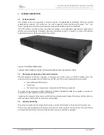
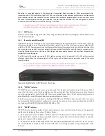
Figure 6 Satellite Router UHP-200 series - front view 

1.5.10


“SYSTEM” Indicator 

“SYSTEM”  indicator  indicates  the  router  operation  mode.  This  indicator  is  always  flashing.  If  it  does  not  flash  it 
means that the router is not functioning (please check power supply).  Slow flashing (once every second)  means 
router  normal  operation.  Faster  flashing  (3  times  every  second)  means  that  a  Telnet  remote  control  session  is 
established (in this case USB console does not operate until session is over). 

Fast (6 times every second), simultaneous flashing of “ERROR” and “SYSTEM” indicators means that the router is 
functioning with the factory default configuration. Access to the router in this mode is possible either via USB of 
via IP-address 192.168.222.222 (mask 255.255.255.248 or /29). 

1.5.11


“ERROR” Indicator 

“ERROR” indicator makes it possible to infer about problems in the router functioning. The type of the generated 
problem can be judged by the number of indicator flashes:  

1 – Demodulator cannot receive SCPC or TDM channel from the other station or the Hub. Please check AGC value 
in the demodulator statistics to determine whether there is a  signal  from antenna  (see description of  reception 
problems) to separate LNB and cable faults. 

2 – Router cannot receive TDMA configuration from the HUB (TDM/TDMA network mode). The reason can be in 
the  non-availability  of  receive  channel  from  the  HUB,  CRC  errors  during  reception,  wrong  configuration  of  the 
Terminal. 

Содержание ROMANTIS UHP-1000

Страница 1: ...HIGH THROUGHPUT SATELLITE ROUTER UHP 200 GENERAL DESCRIPTION AND INSTALLATION GUIDE DOCUMENT RELEASE 3 2 UHP 2R32 EN JULY 2015...

Страница 2: ...1 5 3 Power connector AC IN 9 1 5 4 Expansion slots AUX1 and AUX2 9 1 5 5 LAN interface connectors LAN1 and LAN2 9 1 5 6 USB CONSOLE 9 1 5 7 Modulator output TX OUT 9 1 5 8 RESET button 10 1 5 9 IF sw...

Страница 3: ...settings 17 5 STORAGE TRANSPORTATION AND DISPOSAL 18 FIGURES Figure 1 Structure of UHP Manuals 6 Figure 2 UHP 200 Satellite Router 7 Figure 3 Standard labeling of UHP 200 satellite router 8 Figure 4 U...

Страница 4: ...s messages also known as an error correction code Frame TDMA service packet describing which station should transmit in which time slot Generated 10 times per second Hard priority Method of transmissi...

Страница 5: ...ith the functionality of a very basic form of File Transfer Protocol FTP Timestamp Time format used by UHP Plus sign at the beginning HH MM SS or NN d HH MM SS denotes relative time from some event or...

Страница 6: ...ailable in different fully compatible hardware modifications UHP satellite router is a basic element of any network architecture and can be used in any combinations and at any hierarchy level Router f...

Страница 7: ...ication sheets 1 2 Measurement equipment tools and accessories Standard computer notebook is required to configure and monitor status of UHP 200 satellite router The computer must be equipped with a L...

Страница 8: ...includes 1 Satellite router UHP 200 2 AC Power Cord It is recommended to keep original packaging throughout the entire lifetime Conservation storage and transportation of the terminal must be in orig...

Страница 9: ...ots AUX1 and AUX2 These slots are purposed for interfaces of the optional expansion modules 1 5 5 LAN interface connectors LAN1 and LAN2 LAN connectors are purposed for connecting of the CPE or for ca...

Страница 10: ...of the router can supply 10 MHz reference signal which is required for PLL LNB with an external reference signal When the reference signal is off the router will not distort reference signal arriving...

Страница 11: ...of UHP occurred which prevents software from starting Try to power it off and power on again or press RESET button on rear panel 1 5 12 LOCK Indicator LOCK indicator indicates whether the router recei...

Страница 12: ...ll packing materials for further storage or shipment of equipment 3 Check equipment for the presence of any possible damage resulting from transportation 2 2 2 Installation UHP 200 Router is designed...

Страница 13: ...ter Local Web page of the router can be accessed from any Internet browser By default UHP 200 router is configured with IP address 192 168 222 222 with mask 255 255 255 248 29 Respectively the compute...

Страница 14: ...n be provided to any of IP addresses that are set on the router UHP 200 supports simultaneously only one Telnet session In order the hang session does not block access to the device forever in case on...

Страница 15: ...nctionality by updating the software Software updates also include fixes for known bugs and improving the algorithms of the system 3 2 Powering off To power the router off the Power Supply should be d...

Страница 16: ...ent Verify availability of the carrier and its level with spectrum analyzer Contact Hub administrator and investigate if the carrier is properly transmitting and local weather conditions not attenuate...

Страница 17: ...successfully or if this operation does not eliminate the defect it is necessary to illuminate the faulty device and replace it by new device 4 1 Resetting to default settings To reset user settings yo...

Страница 18: ...d and transported in pallet with height not more than 10 devices Storage and transportation should comply with the following conditions humidity is not more than 80 3 at a temperature 25 2 C limiting...

Отзывы: