Installation and Maintenance Manual
page 10
of 19 -
TIE BAR A95
3 Adjust the length of the bar by screwing and unscrewing the two ball joints of the same size.
DISTANCE BETWEEN
CENTERS OF THE ENGINES
APPROXIMATE LENGTH OF THE BAR
26’’
455 mm (18’’)
27’’
480 mm (19’’)
28’’
508 mm (20’’)
29’’
533 mm (21’’)
30’’
787 mm (22’’)
31’’
584 mm (23’’)
32’’
608 mm (24’’)
34
660 mm (26’’)
36
711 mm (28’’)
37.5’’
747 mm (29.5 ‘’)
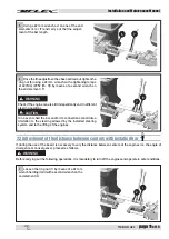
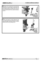
4 Assemble extension arm (1) on the cylinder
body (2) by means of the supplied wrenches (3).
Tighten the screws with a 76[Nm] (56 [lb∙ft]) tight-
ening torque by means of a 14mm wrench.
5 Position the safety washer (4) and fasten it with
screw (5) applying some strong Loctite 270 with a
3[Nm] (2 [lb∙ft]) tightening torque.
The non-use of screw (5) and of safety washer (4)
results in dangers to things and injury of people.
DANGER
3
2
1
5
4
WARNING
WHEN MAXIMUM EXTENSION IS REACHED, DO NOT FORCE THE UNSCREWING BECAUSE THIS CAN DAMAGE
THE PRODUCT.
NOTICE
Be careful not to damage the exposed thread: dents on the thread cause seizure.
L
DANGER
Screw loosening causes deterioration and con-
sequent ineffectiveness of the pre-applied thread
locker. If the screws are loosened, they must be
replaced.
Содержание A95
Страница 1: ...Installation and Maintenance manual Dr No 36010 10 12 2019 PARTNER A95 TIE BAR...
Страница 14: ...Installation and Maintenance Manual page 14 of 19 TIE BAR A95 NOTES...
Страница 15: ...TIE BAR A95 page 15 of 19 Installation and Maintenance Manual NOTES...
Страница 16: ...UFLEX USA Sarasota FL 34243 6442 Parkland Drive...


