background image


S9705-48D Hardware Installation Guide | 24 


11


Initial System Setup 


Establishing a first-time serial connection. 
 
To assign an IP address, you must have access to the command line interface (CLI). The CLI is a text-
based interface that can be accessed through a direct serial connection to the router. 
 
Access the CLI by connecting to the console port. After you assign an IP address, you can access the 
system through Telnet or SSH by Putty, TeraTerm or HyperTerminal.  
 
Perform the following steps to access the router through a serial connection: 


1.


Connect the console cable. 


The console can be connected either with the RJ45 IOIO port or the micro USB port. If 
connecting with micro USB, drivers will need to be installed. 


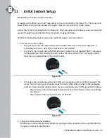
To connect the console using the RJ45 IOIO port, locate the port labelled 

IOIO

, then plug 

a serial cable into the console port and connect the other end to the PC or laptop. Cable 
types may vary depending on the router model. 


Figure 28. 


To connect the console using the micro USB port, locate the port on the front panel of the 
router, then connect your computer using the micro USB cable provided in the packaging 
contents. Download the suitable driver for your operating system (OS) using the URL below: 


https://www.silabs.com/products/development-tools/software/usb-to-uart-bridge- 
vcp-drivers 


https://www.silabs.com/ and search for CP210X 


Figure 29. 


2.


Check for serial control availability. 
Disable any serial communication programs running on the computer such as synchronization 
programs to prevent interference. 

Содержание S9700-53DX

Страница 1: ...Hardware Installation Guide S9705 48D Core Edge Router R1 0 ...

Страница 2: ...PSU Overview 7 Fan Overview 8 Port Overview 9 5 Rack Mounting 10 6 Installing Fan Modules 13 7 Installing Power Supply Units 14 8 Grounding the Router 16 9 Connecting Power 18 DC Version 18 AC Version 20 10 Verifying System Operation 22 Front Panel LED 22 PSU FRU LED 23 Fan FRU LED 23 11 Initial System Setup 24 12 Cable Connections 25 Connecting the USB Extender Cable 25 Connecting the Transceiver...

Страница 3: ...700 23D routers into pay as you grow cluster sizes Suitable for core networking the S9705 48D is one of the essential building blocks to provide carriers with a better solution in place of the traditional chassis With redundant power supplies and fans together with a high port density design our S9705 48D delivers high system reliability switching performance and intelligence to the network and he...

Страница 4: ...low wire for grounding Crimping tool Wire stripping tool All illustrations within this document are for reference purposes only Actual objects may differ PC with terminal emulation software Refer to the Initial System Setup section for details Baud rate 115200 bps Data bits 8 Parity None Stop bits 1 Flow control None ...

Страница 5: ...er circuit Space Clearance The S9705 48D chassis width is 17 16 inches 43 6cm and is shipped with an adjustable mounting rail kit suited for standard 19 inch 48 3cm wide racks The depth of the S9705 48D chassis is 30 inches 76 2cm without the field replaceable units FRUs The handle of fan FRU is 1 inch 2 5cm and the handle of the PSU FRU is 1 5 inches 3 8cm Therefore to accommodate the fan power s...

Страница 6: ...llation spacing requirement S9705 48D chassis spacing requires a height of 2RU 3 45 8 8cm a width of 19 48 3cm and a depth of 42 inches 106 6cm Thermal requirement S9705 48D working temperature is 0 C to 45 C 32 F to 113 F airflow direction is front to back Installation tools required 2 Philips screwdriver wire stripping tools for stripping 6 AWG crimping tool for ground lug Accessories required P...

Страница 7: ...7 5 x 12 5mm 1 pcs 0 03lbs 15 3g 1 pcs 2 Screw Kit for Grounding Lug 2 x Screw M4 L8 0mm 2 x M4 Lock Washers 2 sets 0 01lbs 2 6g 1 set 3 Micro USB Cable 3 28 1m 1 pcs 0 05lbs 24 4g 1 pcs 4 RJ45 to DB9 Female Cable 8 2 4m 1 pcs 0 23lbs 105g 1 pcs 5 Adjustable Mounting Rail for 4 post 30 4 x 1 7 x 0 9 771 x 44 x 22mm 22 33 rack depth 2 pcs 7 01lbs 3 2kg 2 pcs 3 5lbs 1 6kg 1 pcs 6 Screw Kit for Rack ...

Страница 8: ...DC PSU 2 65lbs 1 2kg AC PSU 2 65lbs 1 2kg Fan module 1 10lbs 498g Ground lug 0 15lbs 66 2g Adjustable mounting rail 7 05lbs 3 2kg Micro USB cable 0 05lbs 24 4g RJ45 to DB9 Female cable 0 23lbs 105g AC power cord AC version only 0 70lbs 318g Dimension S9705 48D W x D x H 17 16 x 30 x 3 45 436 x 762 x 87 7mm PSU W x D x H 1 99 x 14 17 x 1 58 50 5 x 360 x 40mm Fan W x D x H 3 15 x 4 80 x 3 15 80 x 12...

Страница 9: ...5 48D Hardware Installation Guide 7 4 Identifying Your System S9705 48D Overview Figure 4 PSU Overview Power supply unit PSU with 1 1 Redundancy Hot swappable field replaceable unit FRU AC Version Figure 5 ...

Страница 10: ...S9705 48D Hardware Installation Guide 8 DC Version Figure 6 Fan Overview 3 1 Redundant hot swappable field replaceable unit FRU Figure 7 ...

Страница 11: ...allation Guide 9 Port Overview Port ID Form Factor Maximum Support Distance Support Speed 0 47 QSFP DD 328ft 100m 400GE The 400G fabric ports of the S9705 48D can only be used to interconnect the S9700 Series routers Figure 8 ...

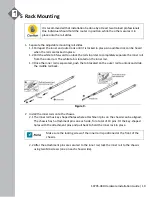
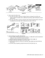
Страница 12: ...rail from the outer rail The white tab is located on the inner rail 1 3 Once the inner rail is separated push the tab located on the outer rail to unlock and slide the middle rail back Figure 9 2 Install the inner rails onto the chassis 2 1 The inner rail has key shaped holes where attachment pins on the chassis can be aligned The chassis has 5 attachment pins on each side for a total of 10 pins F...

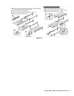
Страница 13: ...be heard when the bracket is secured onto the rack Figure 11 4 Insert the Chassis to complete the installation 4 1 Pull the middle rail fully extended into lock position an audible click can be heard when the middle rail is fully extended and locked into position 4 2 Insert the chassis by lining up the inner rails into the slot of the middle rail 4 3 Slide the chassis into the middle rail until it...

Страница 14: ...S9705 48D Hardware Installation Guide 12 Figure 12 ...

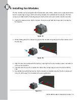
Страница 15: ...an module Then press and hold the release tab to unlock the fan module Figure 13 2 While holding down the release tab grip the fan handle and gently pull the fan module out of the fan bay Figure 14 3 Align the new fan module with the fan bay ensuring that the fan module s power connector is in the correct position 4 Carefully slide the new fan module into the fan bay and gently push until it is fl...

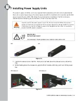
Страница 16: ... power input for AC power supply is only 110V there will only be 1000 watts per power supply and will not be enough power for the power supply to be changed while the router is in operation In order for AC power supply to be changed while the router is in operation ensure that 220V power is supplied Safety Notices Caution Shock hazard TO DISCONNECT POWER REMOVE ALL POWER CORDS FROM UNIT DC AC Figu...

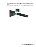
Страница 17: ...e PSU s power connector is in the correct position 4 Carefully slide the new PSU into the power bay and gently push until it is flush with the case 5 An audible click will be heard when the PSU is installed correctly The PSU will not go in all the way if it is in the wrong direction Figure 18 ...

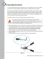
Страница 18: ...g onto the case This equipment must be grounded Do not defeat the ground conductor or operate the equipment without correctly grounding the equipment If there is any uncertainty about the integrity of the equipment s grounding please contact the electrical inspection authority or a certified electrician 1 Before grounding the router ensure that the rack is properly grounded and in compliance with ...

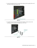
Страница 19: ...for securing the grounding lug which is located on the rear of the router and remove the protective label Figure 20 6 Using 2 M4 screws and 4 washers provided with the package contents firmly lock the grounding lug to the designated grounding location on the router Figure 21 ...

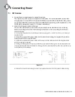
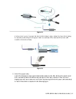
Страница 20: ...lug before connecting to the PSU The following instructions are for connecting the DC Power Cable to the lug 2 1 Strip the insulation from a DC Power Cable leaving 0 5 0 02 12 7mm 0 5mm of exposed cable 2 2 Insert the exposed DC power cable into the heat shrink tubing the length of heat shrink tubing should not less than 38 5mm 2 3 Insert the exposed DC power cable all the way into the hollow tube...

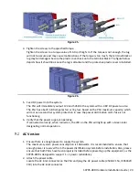
Страница 21: ...alled DC version with insulation material as below Figure 24 3 Attach the power cable Locate the DC power screw type terminal block located on the PSU Remove the plastic cover that is protecting the terminal block by pushing from the top or bottom of the cover and flipping open the cover outwards Secure the two hole lug with the DC power cable attached to the terminal block as depicted in the foll...

Страница 22: ...fuse based on the PSU maximum capacity which will act as a second tier system protection in case the power distribution unit s fuse is not functioning 6 Verify that the power supply is operating If connected correctly when turned on the LED on the PSU will light up with a Green color designating normal operation AC Version 1 Ensure there is enough power to supply the system The maximum system powe...

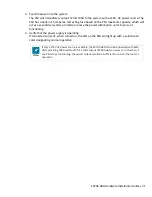
Страница 23: ...he power distribution unit s fuse is not functioning 4 Verify that the power supply is operating If connected correctly when turned on the LED on the PSU will light up with a solid Green color designating normal operation Note If only a 110V AC power source is available the S9705 48D can still be powered with both PSUs providing 1000 watts each for a total output of 2000 watts However in this case...

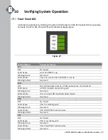
Страница 24: ...lid Amber Power is up but Host CPU BMC is not up Blinking Amber Reserved FAN OFF No FAN modules present or FAN modules are not initialized Solid Green All FAN modules are working well Blinking Green Reserved Solid Amber One or more FAN module s need service Blinking Amber Reserved PS0 OFF No Power Solid Green PSU 0 is working well Blinking Green Reserved Solid Amber PSU 0 fail PSU0 need service Bl...

Страница 25: ...shutdown failure over current short circuit over voltage fan failure and or over temperature Blinking Red 1 sec Input power cord unplugged or input power lost with a second power supply in parallel still with AC input power Blinking between Green and Red Power supply warning events where the power supply continues to operate high temp high power high current and or slow fan Fan FRU LED Additional ...

Страница 26: ...ting with micro USB drivers will need to be installed To connect the console using the RJ45 IOIO port locate the port labelled IOIO then plug a serial cable into the console port and connect the other end to the PC or laptop Cable types may vary depending on the router model Figure 28 To connect the console using the micro USB port locate the port on the front panel of the router then connect your...

Страница 27: ...s the CLI The username and password should be provided by the Network Operating System NOS vendor 12 Cable Connections Connecting the USB Extender Cable Connect the USB 3 0 A Type plug male connector into the USB port female connector located on the front panel of the router Figure 30 Connecting the Transceiver To prevent over tightening and damaging the optic fibers it is not recommended to use t...

Страница 28: ... during handling It is also recommended the cabling be done by a professional who is grounded such as by wearing an ESD wrist strap The following the steps below for connecting a transceiver 1 Remove the new transceiver from its protective packaging 2 Remove the protective plug from the transceiver itself 3 Place the bail wire handle in the unlocked position and align the transceiver with the port...

Страница 29: ...evice ensure that the rack can support it without compromising stability Otherwise personal injury and or equipment damage may result Caution This unit must be installed indoors The unit AC power supplies DC power supplies and its cables are not designed for outdoor use Caution Follow appropriate ESD procedures when unpacking and handling the switch These include unpacking the switch in an ESD saf...

Страница 30: ...rference at his own expense Changes or modifications made to this device which are not expressly approved by the party responsible for compliance could void the user s authority to operate the equipment Industry Canada Notice CAN ICES 003 A NMB 003 A This digital apparatus does not exceed the class A limits for radio noise emissions from digital apparatus set out in the Radio Interference Regulati...

Страница 31: ...the National Electric Code applies The approximate system boot time when the AC or DC power source is connected is 110 secs in Ubuntu Linux system The boot up time would depend on different NOS system The approximate link time for the OOB Ethernet port when reconnected is 40 secs base on Ubuntu Linux system The link time would depend on different NOS system The design of the equipment is that the ...

Страница 32: ...www ufispace com www ufispace com ...

Отзывы: