


22. Indicates the meter is currently recording the maximum and
minimum values.
23.
MIN:
Indicates the meter is displaying the minimum
value recorded.
24.
•
)
)
)
:
Indicates the meter is in the continuity measurement mode.
25.
D.H.:
Indicates the value displayed is held on screen
(the data hold button is pressed).
26.
R.H.:
Indicates the meter is in the manual ranging mode
(the Range button has been pressed).
27.
Function and Units of Measurement:
28.
OFL:
This symbol appears when the input value exceeds
the meters selected range or overall specification.
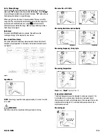
Operating Instructions
Auto Power Off
The instrument automatically shuts off after 30 minutes of inactivity.
The meter is considered active when there is a change of at least 10
digits during the period (i.e., the meter senses a change from 24.04
volts to 24.14 volts)
To disable this function; press and hold the
"MIN/MAX"
or the
"RANGE"
button while turning the meter on. This must be done to
record values for periods longer than 30 minutes.
Back-light / Work light
Press and hold the Data hold / back light button for two seconds. This
will activate the display back light and work area light for 30 seconds.
Pressing the “
D/H
” button again for two seconds will also turn it off.
9.
Rotary Function Switch:
Used to power the meter on and
off, or to select the available measurement functions:
• Measures inductive AC current using the clamp
• Measures capacitance at the test lead inputs
• Measures volts AC or DC Volts at the test lead inputs
• Measures resistance or continuity at the test lead inputs
• Measures Hz and Duty Cycle
• Measures temperature with the K-type thermocouple
and adapter plug at the test lead inputs
• Measures DC microamps using the test lead inputs
CAUTION!
When taking DC current and micro amp measurements, this meter
must be connected in SERIES with the circuit (or circuit element) under
test.
NEVER CONNECT THE TEST LEADS ACROSS A VOLTAGE
SOURCE
while the rotary switch is set to the microamps position. This
can cause damage to the circuit under test or this meter.
10.
Off Position:
Turns the meter off. Always store your meter in
the off position. If the meter will not be used for a month or
more, remove the batteries.
11.
Display:
Communicates function, range and value information
to the user. (See items 16 through 30)
12.
400 µA MAX FUSED:
Indicates that the DC µA ranges are
fuse protected.
13.
Common Terminal:
The black test lead is plugged into this
terminal to supply the ground or “
low
” reference for
all measurements.
14.
MAX 600V
:
Indicates that a maximum of 600 volts
can be applied between the two terminals or between earth
ground and any terminal.
WARNING!
DO NOT
Exceed 600 volts DC or AC-RMS at either the common or
multifunctional input ports, as measured from earth ground in a CAT III
test environment, or 1000 volts in a CAT III test environment.
15.
V
Ω
µA TEMP Terminal:
The red lead is plugged
into this terminal. It is used for AC/DC volts, ohms, continuity,
microamps, diode, capacitance and temperature measurements.
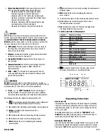
The following describes the indicators displayed by the LCD.
16. this symbol appears when the battery needs replacement.
NOTE:
A low battery will adversely affect accuracy.
17.
AC:
Indicates that alternating current/voltage is being measured.
18.
Minus (—):
Indicates the value measured has a
negative polarity.
19.
DC:
Indicates that direct current/voltage is being measured.
20.
AT:
Indicates the meter is in the autoranging mode.
21.
MAX:
Indicates the meter is displaying the maximum
value recorded.
BAT
R
Symbol
Function or Value
°C
Degrees Centigrade
°F
Degrees Fahrenheit
µF
Micro Farads
mV
Millivolts
V
Volts
µA
Micro Amps (Test Leads)
A
Amps (Inductive Clamp)
M
Mega (Value x 1,000,000)
K
Kilo (Value x 1,000)
Ω
Ohms (Resistance Value)
Hz
Hertz
%
Duty Cycle
DL259-MAN
P. 2
21 22 23 24 25 26
27
28
16
30
17
18
19
20


