


WARNING!
The circuit being tested must be turned
OFF
!
(NO VOLTAGE PRESENT).
• Use the built-in DMM to verify that the circuit under test is
turned
OFF
and no voltage is present.
Measuring resistance (Ohms
Ω
)
1. Slide the ACM6000 power switch to the
ON
position.
2. Turn the rotary function switch to
Ω
.
3. Connect the test leads to the meter.
A. Plug the black lead into the COM input
B. Plug the red lead into the V
Ω
˚F input
4. Verify that the circuit under test has no voltage applied.
5. Connect the test leads across the load or circuit to
be tested.
6. Read the circuit resistance displayed in Ohms.
7. When testing is completed move the instrument
power switch to
OFF
.
Testing continuity
Continuity is the measure of a circuit’s ability to conduct current as
opposed to resisting current flow.
• The Audible Continuity buzzer will sound when resistance
is under approximately 25
Ω
• To set for continuity, follow the same procedures
prescribed for measuring resistance
• The same precautions apply
Measuring temperature
1. Slide the ACM6000 power switch to the
ON
position.
2. Turn the rotary function switch to
˚F
.
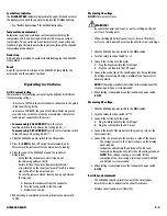
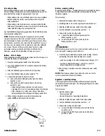
3. Connect the banana plugs of the thermocouple adapter
into the meter inputs (Fig. 1). Observe polarity.
4. Connect the K-type thermocouple to the
thermocouple adapter.
5. The temperature reading can be read on the
display panel.
6. When testing is completed,
move the instrument
power switch to
OFF
.
Plug the standard K-type
thermocouple into this
side of the adapter.
DC current testing
When investigating electrical circuit problems the tools most often
used by the automotive technician are the trouble light and the
volt/ohm meter or DMM. The trouble light is often the tool used to test
for current. However, most trouble lights have severe limitations:
1. The operator must guess at the amp draw based upon the
brightness of the bulb. Modern automotive circuits require precise
current loads. Accurate current measurements are crucial.
2. Many trouble lights require up to 2 amps to shine brightly.
If used to test a circuit designed for less amperage, the 2 amp
draw can over load the circuit resulting in damage.
3. Some DMMs have a built-in current testing feature. When using
most DMM’s to measure amps, it is necessary to open the system
under test and connect the DMM in series. While the test result is
accurate, the hook-up is time consuming and often impractical.
The ACM6000 Clamp Meter is a preferred alternative. By simply
placing the Clamp Meter around a power – or ground - wire of the
circuit being tested, the connection is made. No back probing or
intrusion of insulation is necessary. Additionally, the sensitivity and
resolution of the ACM6000 gives a precise amperage readout rather
than an estimate based upon bulb brightness. Because no direct
connection is required, there is no danger of overloading the circuit.
Re-connecting or reattaching wires is unnecessary.
NOTE:
The ACM6000 Clamp Meter is designed to give accurate
measurement of continuous current flow. If the device being tested
is pulsed (like solenoids and relays) the readout will show the
average current.
For testing recommendations of pulsed circuits contact the UEi Training
Coordinator at 770/476-1431.
Starter current draw
Most starters draw several hundred amps initially, to start the crankshaft
turning. After about one half second the starter current will stabilize for
the duration of cranking. Typical starter current draw (after the initial
surge is):
• 4 cylinder - 120 amps
• 6 cylinder - 150 amps
• 8 cylinder - 180 amps
Test procedure:
1. Disable ignition or fuel, this is a cranking test.
2. Turn the ACM6000 rotary function switch to 200A .
3. Slide the instrument power switch to
ON
.
4. Verify that the vehicle ignition switch is in the
OFF
position.
5. Place the jaws of the ACM6000 around the starter cable and
be sure the jaws are closed.
6. Press the ACM6000
ZERO
button. The display screen should
read approximately 00.0.
ACM6000-MAN
P. 4
(Fig 1)
ATA1 Temp
Probe Adapter


