IMP117-10
www.ueonline.com
GENERAL
BEFORE INSTALLING, CHECK THE SENSOR MODEL SELECTED FOR
COMPATIBILITY BETWEEN THE PROCESS MEDIA AND THE SENSOR
AND WETTED PARTS.
MISuSE OF THIS PRODuCT MAY CAuSE ExPLOSION AND PERSONAL
INjuRY. THESE INSTRuCTIONS MuST BE THOROuGHLY READ AND
uNDERSTOOD BEFORE uNIT IS INSTALLED.
THIS EQuIPMENT IS SuITABLE FOR CLASS I, DIVISION 2,
GROuPS A,B,C,D; CLASS II, DIVISION 2, GROuPS F AND G; CLASS III;
OR NON-HAZARDOuS LOCATIONS ONLY.
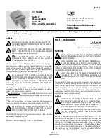
The 117 series pressure and differential pressure switch utilizes a bellows or
diaphragm sensor to detect a pressure change. The response, at a pre-deter-
mined set point, actuates a SPDT or DPDT snap-acting switch, converting the
pressure signal into an electrical signal. Control set point may be varied by
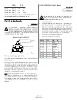
turning the internal adjustment hex. (see adjustment-Part II.)
PROOF PRESSuRE* LIMITS STATED IN THE LITERATuRE AND ON
NAMEPLATES MuST NEVER BE ExCEEDED, EVEN BY SuRGES IN THE
SYSTEM. OCCASIONAL OPERATION OF uNIT uP TO PROOF PRES-
SuRE IS ACCEPTABLE (E.G., START-uP, TESTING). CONTINuOuS OPERATION
SHOuLD NOT ExCEED THE DESIGNATED OVER RANGE** OR WORKING PRES-
SuRE*** RANGE.
*Proof Pressure - the maximum pressure to which a pressure sensor may be
occasionally subjected, which causes no permanent damage (e.g., start-up,
testing). The unit may require re-gapping.
**Over Range Pressure - the maximum pressure to which a pressure sensor
may be continuously subjected without causing damage and maintaining set
point repeatability.
***Working Pressure Range - the pressure range within which two opposing
sensors can be safely operated and still maintain set point repeatability.
WARNING: ExPLOSION HAZARD. THESE PRODuCTS DO NOT HAVE
ANY FIELD REPLACEABLE PARTS. ANY SuBSTITuTION OF COMPO-
NENTS MAY IMPAIR SuITABILITY FOR CLASS I, DIVISION 2.
Please refer to product bulletin for product specifications. Product bulletins
may be found at www.ueonline.com.
Date code format on nameplate is “YYWW” for year and week.
Please read all instructional literature carefully and thoroughly before starting. Refer to the final page for the listing of Recommended
Practices, Liabilities and Warranties.
Part I - Installation
Tools Needed
Adjustable Wrench
Screwdriver
Hammer (for alternate wire knockouts)
MouNTING
WARNING: ExPLOSION HAZARD - DO NOT DISCONNECT EQuIPMENT
uNLESS POWER HAS BEEN SWITCHED OFF OR THE AREA IS KNOWN
TO BE NON-HAZARDOuS.
INSTALL uNIT WHERE SHOCK, VIBRATION AND TEMPERATuRE FLuC-
TuATIONS ARE MINIMAL. MOuNT uNIT SO THAT MOISTuRE IS PRE-
VENTED FROM ENTERING THE ENCLOSuRE. IF uNIT IS BEING
INSTALLED WHERE HEAVY CONDENSATION IS ExPECTED, VERTICAL MOuNTING
(PRESSuRE CONNECTION DOWN) IS REQuIRED. DO NOT MOuNT IN AMBIENT
TEMPERATuRES ExCEEDING PuBLISHED LIMITS.
ALWAYS HOLD A WRENCH ON THE PRESSuRE HOuSING HEx WHEN
MOuNTING uNIT. DO NOT TIGHTEN BY TuRNING ENCLOSuRE. THIS
WILL DAMAGE SENSOR AND WEAKEN SOLDERED OR WELDED
jOINTS.
Controls may be mounted and operated in any position. They may be sur-
face mounted via the two mounting ears on either side of the enclosure, or
directly to a rigid pipe by using the pressure connection. Low pressure and
differential pressure units, models 520-535, 540-548, are also available with
an optional surface mounting bracket. Should the control be installed where
condensation is expected, vertical mounting is recommended as a means of
keeping water away from switch terminals.
WIRING
DISCONNECT ALL SuPPLY CIRCuITS BEFORE WIRING uNIT. WIRE
uNITS ACCORDING TO NATIONAL AND LOCAL ELECTRICAL CODES.
MAxIMuM RECOMMENDED WIRE SIZE IS 14 AWG. THE RECOM-
MENDED TIGHTENING TORQuE FOR FIELD WIRING TERMINALS IS 7
TO 17 IN-LBS. uSE 75
°
C RATED COPPER CONDuCTORS ONLY.
ELECTRICAL RATINGS STATED IN LITERATuRE AND ON NAMEPLATES
MuST NOT BE ExCEEDED. OVERLOAD ON A SWITCH CAN CAuSE
FAILuRE ON THE FIRST CYCLE.
Remove the two screws retaining the cover and cover gasket. A 1/2” NPT
conduit connection is provided on the left hand side of the enclosure. Two
cast-in 7/8” diameter knockouts for electrical conduit are located on the
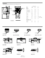
side and back of enclosure (see dimensional drawings). These can easily be
knocked out by placing a blade of a screwdriver in groove and tapping sharp-
ly with a hammer. The terminal block terminals are clearly labeled “Common”,
“Normally Open” and “Normally Closed”. For units supplied with DPDT, all
terminals are labeled and the following color code applies.
117 Series
Type H117
(Pressure Switch)
Type H117K
(Differential Pressure Switch)
IMP117-10
U N I T E D E L E C T R I C
C O N T R O L S
Installation and Maintenance
Instructions


