background image

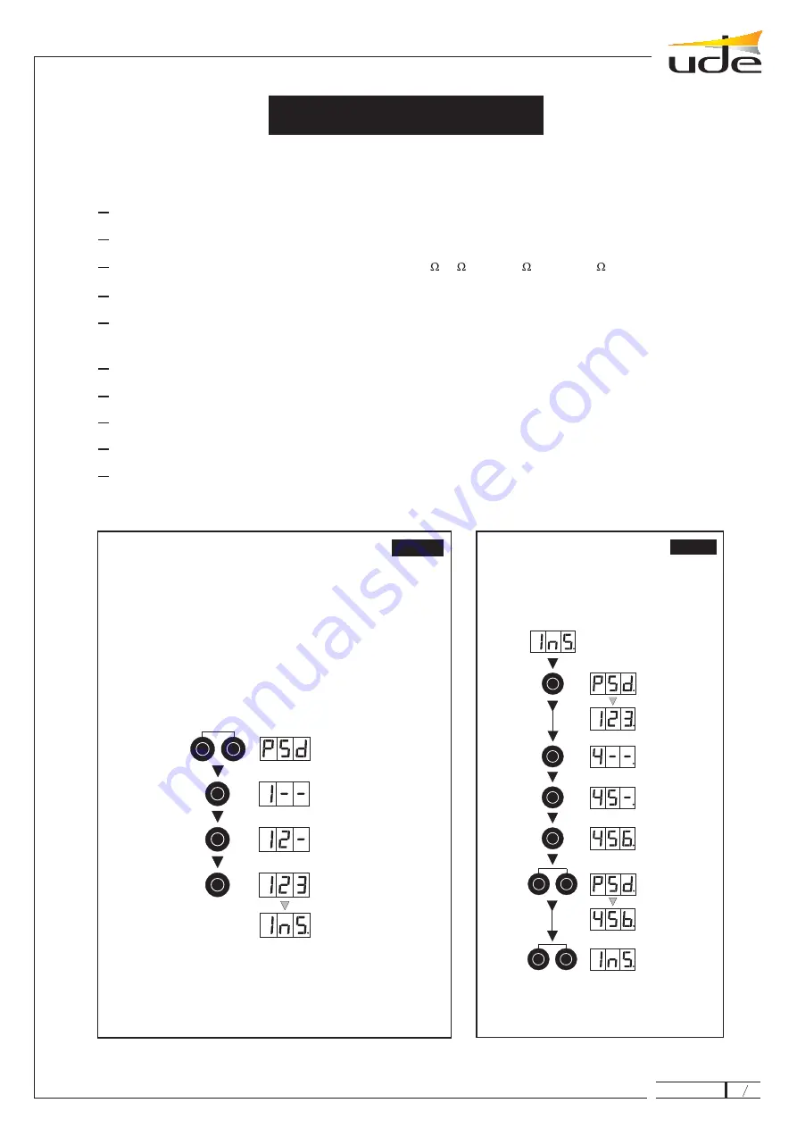
The installer can use the keyboard and associated display to perform the following
operations:

PASSWORD
SELECTION

1 DIGIT
PASSWORD

2 DIGIT
PASSWORD

3 DIGIT
PASSWORD

INSTALLER
MENU

INSTALLER
MENU

1

2

3

F

8

Fig. 1

ACCESS
INSTALLER MENU

INSTALLER MENU

F

5

7

ACCEPT
NEW
PASSWORD

4

from nº 1

to nº 8

PASSWORD
SELECTION

CURRENT
PASSWORD

1 DIGIT
OF NEW
PASSWORD

2 DIGIT
OF NEW
PASSWORD

3 DIGIT
OF NEW
PASSWORD

5

6

from nº 1

to nº 8

froml nº 1

to nº 8

F

1

Fig. 2

CHANGE
PASSWORD

Access the installer menu

.

Change the password in the installer menu

.

Select the load impedance of the unit manually (4 , 8 , 70V/16 , 100V/33 ).

.

Match load the impedance to the unit automatically

.

Change and memorise volume, treble and bass settings in the memory of the standard
operation mode for the unit, and restore default values (factory settings)

.

Record programmes

.

Copy content from one programme to another

.

Edit (correct) an existing programme

.

Select the unit’s operating mode (mode 1 / mode 2)

.

Return to the user menu

.

(Fig. 1)

(Fig. 2)

(Fig. 3)

(Fig. 4)

(Fig. 5)

(Fig. 6)

(Fig. 7)

(Fig. 8)

(Fig. 9)

(Fig. 10)

Press the “F” key and then, while you hold down the
aforementioned key, press key “8”
The display will show “PSD”, whereupon you key in the 3-
figure password.
The factory-set password is “123”
The display will show “123” followed by “INS” (Installer)
If you make a mistake with the password the display will show
“USU” (user) and will revert to the initial status.
The sequence is as follows:

NOTE:

If you are unable to access the installer menu because

you cannot remember the password, press the rear reset
button using a suitable object, whereupon “RES” will appear
on the display, and the password is “123”.

ST

ST

nd

nd

rd

rd

AX-309

16

11

610.104A

Содержание AX-309

Страница 1: ...put level 800 mV impedance 600 Insertion output 400 mV 600 input 400 mV 4700 4 8 300 W RMS five input power amplifier with built in mixer for professional audio applications Microprocessor controlled...

Страница 2: ...gital control Display Bass digital control Treble digital control Microprocessor functions selector Push button for programming and function Mixer bus input Insertion input output 1 0 dBm signal outpu...

Страница 3: ...vation of automatic protection switches or the blowing of fuses in the electrical panel which are typical in other high power units The installing engineer may access the load impedance menu and make...

Страница 4: ...me control Inputs 1 2 3 and 4 are configurable Balanced microphone phantom power supply and equalizer filter for voice Auxiliary One direct signal input to the mixing bus for input expansion Signal in...

Страница 5: ...r the connection diagram according to specific requirements Special care should be taken to comply with any applicable safety standards Do not block the front and rear air vents in order to make sure...

Страница 6: ...MICROPHONE JUMPER SETTINGS VOICE MICROPHONE PHANTOM POWER SUPPLY VOICE MICROPHONE MUSIC MICROPHONE PHANTOM POWER SUPPLY Configuration of convertible inputs REMOVE THE COVER AND SET THE JUMPERS AS FOL...

Страница 7: ...IC CONNECTION SYSTEM WX 30 Chime and priority module WX 33 Simple priority module WX 19 Antilarsen module AUXILIARY AMPLIFIER CA 01 CA 32 CA 01 Connection diagram OPTIONAL ELEMENTS MICROPHONE SOUND SO...

Страница 8: ...3 handle bracket mounting rack 1 2 WX 19 3 WX 19 4 5 D 6 Remove the top cover of the unit Remove the bracket for the module Assemble the module in the aforementioned bracket using the screws supplied...

Страница 9: ...the screws supplied Fit leads and as shown Fix the bracket iron in position The unit is ready to operate Adjust the tone and level of the chime if necessary Refit the cover 1 2 WX 33 3 WX 33 4 A 5 6...

Страница 10: ...C AUX 3 MIC AUX 4 MIXER 0 dBm OUTPUT INSERTION AUX 5 TM1 TM2 TM3 TM4 TM Mix TM TM 1 2 3 4 and Mix DIGITAL CONTROL CONTROL DIGITAL SIGNAL 92 VDC MASTER Th 65 C P _ 230 VAC VOL 1 VOL 2 VOL 3 VOL 4 VOL 5...

Страница 11: ...dard operation mode for the unit and restore default values factory settings Record programmes Copy content from one programme to another Edit correct an existing programme Select the unit s operating...

Страница 12: ...PROGRAMME 1 F 1 1 F 5 from n 1 to n 8 Fig 6 RECORDING PRESET PROGRAMMES fig 5 2 MANUAL ADJUSTMENT CURRENT IMPEDANCE VALUE NEW IMPEDANCE VALUE INSTALLER MENU Z 4W Z 8W L 70V L 100V F F F 1 2 3 F 4 F 5...

Страница 13: ...3 F 1 3 F 5 del n 1 al n 8 Fig 7 COPY THE CONTENT OF ONE PROGRAMME TO ANOTHER E g copy programme 2 to 3 8 ACCORDING TO SELECTED OPERATING MODE MODE 1 STANDARD MODE 2 PROGRAMMED Fig 10 RETURN TO USER...

Страница 14: ...ral volume if necessary If the amplifier stops working and shows the message this means that the internal control device has switched off the unit s power supply This may be due to two reasons The int...

Страница 15: ...TART UP ON MOD OFF ON Operation with remote controlled message priority INDICATE VOLUME VALUE MESSAGE PRIORITY MENU ISSUE PRIORITY MESSAGE REMOTE CONTROLLED MESSAGE PRIORITY NOTE During the issue of a...

Страница 16: ...AMME 1 VOLUME Volume Value TREBLE Treble Value BASS SELECTED PROGRAMME Bass Value F 4 PROGRAMME 1 PROGRAMME 2 PROGRAMME 3 PROGRAMME 4 PROGRAMME 5 PROGRAMME 6 PROGRAMME 7 PROGRAMME 8 1 2 3 4 5 6 7 8 ST...

Отзывы: