


EVK-MAYA-W2 - User guide
UBX-22011269 - R04
Board description
Page 15 of 20
C1 – Public
The M.2 interface signals M2_UART_WAKE#, M2_W_DISABLE1#, and M2_W_DISABLE2# use 3.3 V
signal voltage with voltage translators on the EVB. See
for details. All other signals are
powered from the board VIO voltage.
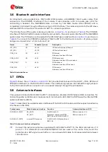
Figure 9: M.2 card ZIF connector (J2) and pin headers J4 and J5
The M.2 Key E pinout follows the definition from NXP for M.2 sockets on platforms based on NXP
MPUs and MCUs. For more information about the Wi-Fi/Bluetooth M.2 Key E Pinout Definition on NXP
host boards, see also the NXP AN13049 pin definition
☞
Some interfaces might not be available on the M.2 socket of a host platform. Check the
interface connector specification from the host platform vendor to confirm the pinout and
supported interfaces.
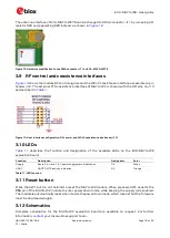
3.5.3
SPI host interface for IEEE 802.15.4
shows pin header J13 which provides direct access to the SPI interface for the IEEE
802.15.4 radio on EVK-MAYA-W271 and EVK-MAYA-W276.
Figure 10: SPI interface connector (J13)


