background image


U9016B Installation Guide 

17 

PON 

              OLT 

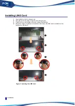
Uninstalling the LINE Card 

1. 

Press the each lever of ejectors and pull out the each hinge from each hole. 

2. 

Pull out the each side hinge of ejector from the hanging pin of a chassis. 

3. 

Take the end of ejector lever and pull it backward powerfully. 

4. 

While the ejectors unfold more, the LINE Card is separated from the backplane socket. 


Figure 6. Unistalling the LINE Card 


Содержание U9016B

Страница 1: ...PON OLT U9016B For GPON Installation Guide...

Страница 2: ...II U9016B Installation Guide UbiQuoss Inc 24F Millennium B D 467 12 Dogok Dong Gangnam Gu Seoul 135 700 Korea TEL 82 70 8666 5000 FAX 82 2 2190 3201 E mail oversea team ubiQuoss com www ubiQuoss com...

Страница 3: ...rience of installing and managing network devices Consequently see other network related references for the professional terms that are not explained in this user guide Related Documents U9016B switch...

Страница 4: ...ion can occur and provides the proper actions to take in the situation Warning Describes the situation that product damage and the user s injury can occur and provides the proper actions to take in th...

Страница 5: ...ng the product The user should fully understand the notes in this chapter before installing the product to prevent any problem that may occur during the installation of product Chapter 3 Installation...

Страница 6: ...re Installation 8 Do not disassemble the product 8 Installation site condition 8 Satisfying operational environment conditions 8 Prevent static electricity 8 Notes to take when using power 8 Grounding...

Страница 7: ...4 Troubleshooting 25 Troubleshooting Case 26 Appendix A Product Spec 29 Overview 29 Specification 29 Layer 2 Features 29 Layer 3 Features 30 QoS Features 30 Security Features 30 System Security Featur...

Страница 8: ...VIII PON OLT List of Tables Table 1 Description on each U9016B unit 3 Table 2 LED for each U9016B unit 4 Table 3 List of items necessary for Installation 11 Table 4 List of Package Items 12 Table 5 C...

Страница 9: ...2 SCU 3 Figure 3 PIU 8G 3 Figure 4 Rear and Side 5 Figure 5 Installing the LINE Card 16 Figure 5 Unistalling the LINE Card 17 Figure 5 U9016B AC Connecting Power 18 Figure 6 U9016B DC Connecting Power...

Страница 10: ...List of Figures Introduction X PON OLT...

Страница 11: ...ation Guide 1 PON OLT Chapter 1 Introduction This chapter introduces the product types and features of U9016B and the name and function of each part as well The chapter consists of the followings Over...

Страница 12: ...dedicated PON OLT slots Structure of PON OLT ubiQuoss PON OLT system consists of Optical Line Terminal OLT that is connected to the Internet Core Network in the Central Office performs IP routing and...

Страница 13: ...U PA AC 100 240 VAC 50 60Hz Power Module Supporting redundancy Common part PSU PD DC 48 VDC Power Module Supporting redundancy Common part FMU Fan Module Unit Modular unit Common part PIU 8G GPON 2 5G...

Страница 14: ...ANGE ON FAN Alarm status LNK ACT GREEN ON Management Ethernet Link Up BLINK Management Ethernet TX RX status P1 P6 GREEN ON P1 P6 Uplink Port Link Up BLINK P1 P6 Uplink Port TX RX status PSU PWR GREEN...

Страница 15: ...ct from being overheated Figure 4 Rear and Side Caution U9016B has the structure that the Fan Module FMU is located on the side of the device Consequently if the left side and the right side of the de...

Страница 16: ...power redundancy each power input terminal should be connected to different power sources In case a power supply has a problem and fails to provide power properly the power redundancy function allows...

Страница 17: ...U9016B and notes for installing and using the product The user should fully understand the notes in this chapter before installing the product to prevent any problem that may occur during the installa...

Страница 18: ...oid the location where an electro magnetic wave is generated Install the product in the location that the user can easily access and connect a cable to the product easily Satisfying operational enviro...

Страница 19: ...power cables Grounding For the electric safety the product supervisor and user should check the grounding status before supplying power to the product and ground the product using the ground hole on t...

Страница 20: ...that can cause an injury to a person or damage to the device Checking the installation environment This section describes the necessary installation environment to install and use U9016B safely It is...

Страница 21: ...user should prepare these before the product installation Table 3 List of items necessary for Installation U9016B Main Body U9016B Installation User Guide a book or a manual CD Power Cord Console Cabl...

Страница 22: ...bles A manual CD that includes a release note a user guide a command guide and a configuration user guide AC Power cable 2 EA The cables to supply power DC Power cable is optional Console cable 1 EA T...

Страница 23: ...9016B onto a rack and connect each port of the device The chapter consists of the following sections Selecting an Installation Site Installation onto a Rack Connecting Power Connecting a Console Termi...

Страница 24: ...void the top of a shaky shelf a tilted location or a place with big vibrations Avoid the location where an electro magnetic wave is generated Keep the surroundings of the product clean and dust free d...

Страница 25: ...oduct U9016B size 482X295X88 8 mm 4 Two workers should work together to put the product with the rack brackets attached on the installation site of the 19 rack 5 Align the rack brackets attached to th...

Страница 26: ...he chassis rail 2 Hang the each side hinge of ejector at the hanging pin 3 Press the lever with fingers and push it forward powerfully 4 When the hinges of ejectors are inserted in the holes the LINE...

Страница 27: ...ll out the each hinge from each hole 2 Pull out the each side hinge of ejector from the hanging pin of a chassis 3 Take the end of ejector lever and pull it backward powerfully 4 While the ejectors un...

Страница 28: ...ut terminals and then connect the plugs to different power sources Figure 7 U9016B AC Connecting Power DC power Connect the 48V DC power supplied from the rack to two 48V power input terminals and the...

Страница 29: ...Power consumption Max 160 Watt based on full installation Input frequency 50 60Hz The power for the U9016B using DC should satisfy the following specifications Input Voltage DC 48 VDC Power consumpti...

Страница 30: ...set according to the following communication environment conditions so that it can communicate with U9016B normally Bit Rate 9600 bps Data Bit 8 bit Stop bit 1 bit Parity bit None Flow control None F...

Страница 31: ...the switch connected to the network If a cable is connected to the management Ethernet port when power is supplied to U9016B it is possible to check the network connection status through the LED opera...

Страница 32: ...ly with LED indicators As described before connect a console terminal using the console port of the device and set the communication environment of the console terminal If the console terminal is conn...

Страница 33: ...example of setting the IP address to 10 1 13 220 U9016B config int eth0 U9016B config if eth0 ip address 10 1 13 220 24 U9016B config if eth0 end 9 To view the IP address previously set the mode shou...

Страница 34: ...Operation Checking Installation 24 PON OLT...

Страница 35: ...olve them Many of the problems occurring to the device are what the user can check and resolve easily If the device fails to operate normally see the description in this chapter and check if the probl...

Страница 36: ...tch and then turn it on to run the device again Problem 3 No character is displayed on the console terminal screen or the displayed characters are broken An improper console cable is connected or the...

Страница 37: ...de 27 PON OLT 1 Check if the connector of the cable is inserted into the port properly 2 Check if the connected device is operating normally 3 Check if the cable used for the port satisfies the specif...

Страница 38: ...Troubleshooting Case Troubleshooting 28 PON OLT...

Страница 39: ...4 port 1000Base X SFP 2 port 10GBase R SFP Management Interfaces 10 100Base TX RS 232 Console Power Supply AC type 100 240 VAC 50 60Hz DC type 48 VDC Dimension WxDxH Main body 429 2mm x 88 8mm x 295mm...

Страница 40: ...CP COS Packet Drop Mirroring to Port Redirect to Port Metering Rate Limiting with 1Mbps unit QoS Tables COS Queue DSCP Queue Queue 8 queues per port SPQ DWRR Hybrid SPQ DWRR Rate Shaping Egress rate s...

Страница 41: ...ookies CPU packet rate limit Management Management packet priority control Others Gratuitous ARP System Information Line Item PBA Description Quantity SCU SCU PON OLT system Switch Control Unit 4 1000...

Страница 42: ...Troubleshooting Case Troubleshooting 32 PON OLT...

Страница 43: ...Installation Guide 33 PON OLT Appendix B Cable Spec Appendix B describes the specifications of the cable used to connect the ports of U9016B Appendix B consists of Ethernet cable Optical cable Console...

Страница 44: ...se the one of a proper category depending on the device speed 10M Category 3 4 100M Category 5 1000M Category 5 5 6 Optical cable For the GPON link of U9016B use the single mode optical cable that has...

Страница 45: ...r on one side and an RJ 45 connector on the other side as describe below The table below describes the types of the signals transmitted from each pin of the connectors on both sides of a console cable...

Страница 46: ...Troubleshooting Case Troubleshooting 36 PON OLT...

Отзывы: