Ubert HT Series Скачать руководство пользователя страница 12

12 

Installation and putting into operation 

printed: 02/2015  Subject to change! 


 TopLineUserManualHT.docx 
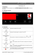
Installation and putting into operation 

In general all  Hot Cabinets will be packed for safe transport after the final control in 
order to reach you properly. Nevertheless we ask you to have a look at the machine 
on arrival to detect any transport damages if there are any. 

Note! 

Visible damages have to be reported immediately! 


4.1  Unwrapping 

  Open the carton and take out the wrappingmaterial carefully. 

  Take care that the delivery is complete (see attached freight papers). 

4.2  Installation 

Place  the  Hot  Cabinet  in  the  desired  location.  Make  sure,  that  is  is  good  visible for 
your customer to ensure good foodpresentation and successfull sales. 
 
Take care of the following points: 

  The Hot Cabinet has to be placed on a horizontal level. Use a spirit level if neces-

sary.  

  Take  care that  both  sides have  at  least 10cm  clear  space  to  enable  cleaning  of 

the sideglasses. 

  There has to be enough free space to load, unload, clean and maintain the unit. 

  The machine has to be placed so that the complete area around it can be cleaned 

easily. 


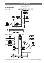
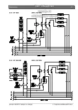
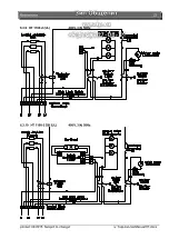
4.3  Electrical connection 

Note!

  In  general,  only  service  technicians  of  the  company:  UBERT  GASTRO-

TECHNIK  GMBH  or  service  technicians  of  your  responsible  service  partner  are  al-
lowed  to  perform  el.  connection  and  other  service!  All  national  and  lokal  rules  and 
regulations  concerning  electricity,  fireprotection  and  the  like  have  to  be  concidered. 
During any servicing, take care that the unit is disconnected from the mains! Not pay-
ing attention may result in injury! 


Please learn the electrical and technical data of your unit from the nameplate. 

  Check whether your lokal electrical power supply is in accordance with the values on the name 

plate. 

  Make sure the supply cable is protected as listed below: 

(3- wire, min. cross-section 1,5

) separatly with 16 Amps. 

  UL-versions: For supply wire gauge note the specification as shown to the terminal block inside 

the unit. 

  The power supply needs to be manufactured from heat resistant, flexible cable. It is to be rou ted 

to prevent any contact to hot parts. 

  The unit is to be connected to the power supply either by means of an appropriate plug or if con-

nected permanently, a switch (interupting all poles) is to be provided. In case of an emergancy 
the power supply must be interuptable immediately. 

  For further information please see the wiring diagram (below). 

Note!


After finishing any installationwork, maintainance or repair check whether the ground 
wires are connected properly to the casing. 


Содержание HT Series

Страница 1: ...User Manual HOT DISPLAY CABINET HT Series...

Страница 2: ......

Страница 3: ...6 3 Introduction 8 3 1 Introduction 8 3 2 Special features 8 3 3 Technical details 9 4 Installation and putting into operation 12 4 1 Unwrapping 12 4 2 Installation 12 4 3 Electrical connection 12 4 4...

Страница 4: ...e examined regularly 2 1 3 Obligation of the personnel All induviduals who are authorized to work with the unit are obliged to pay attention to the fundamental regulations of work safety and accident...

Страница 5: ...e of wear and tear parts Unauthorized repair Force of nature and act of god 2 3 Symbols and Notes In the operating manual the following symbols and signs are used This symbol means a possibly or direc...

Страница 6: ...etermined clearly for installing start up operation assembling and servicing of the unit During instruction the personal may only work at the unit under supervision of an experienced person 2 5 4 Unit...

Страница 7: ...unintended reclosing Check all screw connections for tight fitting After finishing maintenance check all safety devices for proper functionality 2 5 9 Structual changes to the unit Do not perform any...

Страница 8: ...he optimized constant climate guarantees long holding times at low quality loss To optimize the product presentation the cabinet is equipped with an effective hallogen lighting The maximum holding tim...

Страница 9: ...Introduction 9 printed 02 2015 Subject to change TopLineUserManualHT docx 3 3 Technical details 3 3 1 Dimensions mm HT 700 HT 700 DB HT 100 HT 1100 DB...

Страница 10: ...r HT 700 230V 1 N 50Hz 2 8 kW HT 1100 400V 3 N 50Hz 4 2 kW HT 1400 400V 3 N 50Hz 5 6 kW HT 700 DB 230V 1 N 50Hz 2 82 kW HT 1100 DB 400V 3 N 50Hz 4 23 kW HT 1400 DB 400V 3 N 50Hz 5 63 kW HT 700 2 208V...

Страница 11: ...Introduction 11 printed 02 2015 Subject to change TopLineUserManualHT docx all types 70 dB A...

Страница 12: ...service technicians of the company UBERT GASTRO TECHNIK GMBH or service technicians of your responsible service partner are al lowed to perform el connection and other service All national and lokal r...

Страница 13: ...abinet you have to clean all removable parts carefully with a grease sol vent Note Do not use flammable cleaners Do not use high pressure water pressure or steam jet cleaning machines You will have fu...

Страница 14: ...s the cabinet ON and OFF LIGHT Button Switches the lights inside the cabinet ON and OFF PPROGRAMMING button Keep pushed to change the set temperature using and UP button While is pushed use the UP but...

Страница 15: ...the tools you require during operation Cutting Board Workspace to cut your products and do various other han dling during loading unloading packing and the like Note Do not place hot GN pans or other...

Страница 16: ...wards so that there are no residues of the cleaner on these parts It is absolutely necessary to watch out for some fundamental things to keep this longliving high grade steel machine working always ke...

Страница 17: ...elow some special cleaning tips for this specific unit Lamps To be cleaned only with soft paper or cloth and alcohol Glass Tip the cuved front glass to clean the inside Remove dust and dirt from the g...

Страница 18: ...hese two companies are allowed to carry out service work and replacement of defect parts If you do not observe this note or in case of manipulation of a third party any claims for guarantee will becom...

Страница 19: ...Maintenance 19 printed 02 2015 Subject to change TopLineUserManualHT docx 6 3 Wiring Diagrams 6 3 1 HT 700 230V 1 N 50Hz 6 3 2 HT 700 DB 230V 1 N 50Hz...

Страница 20: ...20 Maintenance printed 02 2015 Subject to change TopLineUserManualHT docx 6 3 3 HT 1100 400V 3 N 50Hz 6 3 4 HT 1100 DB 400V 3 N 50Hz...

Страница 21: ...Maintenance 21 printed 02 2015 Subject to change TopLineUserManualHT docx 6 3 5 HT 1400 400V 3 N 50Hz 6 3 6 HT 1400 DB 400V 3 N 50Hz...

Страница 22: ...22 Maintenance printed 02 2015 Subject to change TopLineUserManualHT docx 6 3 7 HT 700 2 UL 230V 1 N 50Hz 6 3 8 HT 700 2 DB UL 230V 1 N 50Hz...

Страница 23: ...Maintenance 23 printed 02 2015 Subject to change TopLineUserManualHT docx 6 3 9 HT 1100 2 UL 400V 3 N 50Hz 6 3 10 HT 1100 2 DB UL 400V 3 N 50Hz...

Страница 24: ...24 Maintenance printed 02 2015 Subject to change TopLineUserManualHT docx 6 3 11 HT 1400 2 UL 400V 3 N 50Hz 6 3 12 HT 1400 2 DB UL 400V 3 N 50Hz...

Страница 25: ...ed out only by their service personal or by your authorized Service companies If you do not observe this note or in case of manipulation of a third party any claims for guarantee will become invalid A...

Страница 26: ...121044 1 17 drawer 120520 1 1 18 crumb tray 120611 2 19 tumber switch 341108 2 20 thermometer 0 C to 120 C HT700 HT700DB 342907 1 20 thermometer 30 F to 250 F HT700 2 HT700 2DB 342912 1 21 knob 36131...

Страница 27: ...awer 120552 1 1 18 crumb tray 120612 2 19 tumber switch 341108 1 20 thermometer 0 C to 120 C HT1100 HT11000DB 342907 20 thermometer 30 F to 250 F HT1100 2 HT11000 2DB 342912 1 21 knob 361311 1 22 disp...

Страница 28: ...28 Maintenance printed 02 2015 Subject to change TopLineUserManualHT docx...

Страница 29: ...tray left right 120613 2 18 crumb tray middle 120614 1 19 tumber switch 341108 2 20 thermometer 0 C to 120 C HT1400 HT1400DB 342907 1 20 thermometer 30 F to 250 F HT1400 2 HT1400 2DB 342912 1 21 knob...

Страница 30: ...30 Maintenance printed 02 2015 Subject to change TopLineUserManualHT docx...

Страница 31: ...5A 335091 HT 700 2 DB 335091 HT 1100 2 DB 335091 HT 1400 2 DB terminal block 333323 HT 700 2 DB 333323 HT 1100 2 DB 333323 HT 1400 2 DB end cap for terminal block 333324 HT 700 2 DB 333324 HT 1100 2...

Страница 32: ...32 Maintenance printed 02 2015 Subject to change TopLineUserManualHT docx 6 5 Declaration Of Conformity...

Отзывы: