12
Operation
© 2010 ICS, Blount International Inc. Specifications are subject to change without notice. REV0611 F/N 545067
TITLE
695GC / 695F4 OPERATOR’S MANUAL
13
COLD ENGINE STARTING PROCEDURE
1. Pull the choke lever out, which also sets the throttle lock.
2. Depress primer bulb approximately 5-10 times.
3. Push in decompression valve.
4. Open the water valve 1/4 turn.
5. Place the saw on stable ground making sure the chain
is free of any obstructions.
6. Place foot on the base of the rear handle, and place one hand
on front handle.
7. With opposite hand, slowly pull starter handle until the
starter pawls engage.
8. Pull the starter cord (
hard, fast, short pulls
)
until engine initially fires or "pops"
.
Could be as many as 10-15 pulls.
9.
Push the choke lever in.
10. Pull the starter cord until engine starts - should be 1 to 2 pulls.
11. Release the throttle lock by momentarily squeezing on the
throttle trigger.
12. When the engine starts, allow the engine to idle briefly.
Squeeze the throttle trigger several times to help
warm up the engine.
13. Open the water valve completely.
CAUTION
STARTING AND STOPPING A CONCRETE CHAIN SAW
Never start a concrete chain saw without the bar, chain and side
cover properly assembled. Failure to do so may result in serious
injury.
Always move a concrete chain saw at least 10 feet (3 m) away
from the fueling area before starting.
Place the saw on clear ground. Ensure that secure footing is
established and chain is not contacting any objects.
IMPORTANT
WARNING
WARM ENGINE STARTING PROCEDURE
1. Use the same procedure as starting a cold engine, but pull choke lever out, and
then push back in
to set
the throttle lock. If choke is used on a warm engine, the carburetor will flood with gas.
2. If the engine does not start in 3 hard, fast pulls with the throttle locked, fully squeeze and hold the trigger
while pulling the starter cord 3 more times.
Note: To hold the trigger fully open it may be necessary to insert right foot into rear handle opening
and twist.
STOPPING THE SAW
• To turn the engine off, push stop switch to the "STOP" position. Close water valve.
OPERATION
Throttle Trigger
Trigger Interlock
Decompression Valve
Stop Switch
Primer Bulb
Choke
Lever
© 2010 ICS, Blount International Inc. Specifications are subject to change without notice. REV0611 F/N 545067
TITLE
695GC / 695F4 OPERATOR’S MANUAL
14
PRE-CUT CHECKLIST
• Ensure proper chain tension: The chain should be easily pulled around the guidebar by hand.
• Ensure all safety devices are properly mounted and functional and that all controls are in proper
working order.
• Be sure there are no obstructions (plumbing, electrical conduit, air ducts) and no unnecessary
people present.
• Always wear protective clothing, including hard hat, eye protection, hearing protection, non-slip
safety boots, and gloves. Avoid wearing loose fitting clothing.
• Adequate Water Supply and Pressure:
Minimum Flow: 2 gpm (8 lpm)
Minimum Water Pressure: 20 psi (1.5 bar)
• Diamond chains with SealPro
®
require a minimum
water pressure of 20 psi (1.5 bar).
PLANNING THE CUT
• Select the proper chain type for the material being cut.
• Outline the cut with a permanent marker for a visual cutting guide.
• Avoid pinching the guidebar and chain. Always cut the bottom of an opening first, then top, and
then the sides. Save the easiest cut for last.
• For the straightest cuts use the “Step Cut” method. First score the entire cut line approximately a
half-inch deep using the nose of the bar. Next, deepen the cut by about two inches. Then plunge
all the way through and complete the cut using the WallWalker
®
.
• Be sure cut concrete cannot fall and injure operator or bystanders. Concrete is very heavy,
one cubic foot = 12 in x 12 in x 12 in = 150 lbs (30 cm x 30 cm x 30 cm = 68 kg).
• Check for and remove any obstructions (plumbing, electrical conduit, air ducts, etc,) that may
interfere with the cut.
The single most important factor an operator can control to
increase chain life is to use adequate water pressure. Insufficient
water supply will result in excessive wear to the chain, which can
lead to loss of strength and chain breakage, and/or damage to the
guidebar nose sprocket.
IMPORTANT
OPERATION
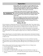
Never start a diamond chain saw without the bar, chain and side cover
properly assembled. Failure to do so may result in serious injury.
Always check hose connections before turning on air compressor.
Hold saw with both hands and ensure the chain is not contacting any
objects.
• Ensure Proper Chain Installation: Concrete chains should lead with the bumper segment into the cut.
Ductile chains can be mounted in either direction.
• Ensure Proper Chain Tension: The chain should be tight but easily pulled around the bar by hand.
• Ensure all safety devices are properly mounted and functional. Ensure all controls are in working order.
• Be sure there are no obstructions (plumbing, electrical conduit, air ducts, etc.) and no unnecessary
people present.
• Always wear protective clothing, including hard hat, eye protection, hearing protection, non-slip safety
boots, and gloves. Avoid wearing loose fitting clothing.
• Use Adequate Water Supply and Pressure:
Minimum Flow: 1gpm
Recommended Water Pressure: 20psi
• Use Proper Air Supply:
Minimum PSI : 90
Minimum CFM: 90
• Blow the air supply line clear before connecting to the saw.
• Check oil level; if necessary, re-fill oiler with ice-free air tool oil.
• The chain should travel away from the operator on the top side of the bar during operation.
Pre-Cut Checklist
The single most important factor an operator can control to increase
chain life is to use adequate water pressure. Insufficient water supply will
result in excessive wear to the chain which can lead to loss of strength
and chain breakage and/or damage to the guidebar nose sprocket.
• Select the proper chain type for the material being cut.
• Outline the cut with a permanent marker for a visual cutting edge.
• Avoid pinching the guide bar and chain. Always cut the bottom of an opening first, then top, and then
the sides. Save the easiest cut for last.
• For the straightest cuts in concrete use the “Step Cut” method. First, score the entire cut line approxi
-
mately a half-inch deep using the nose of the bar. Next, deepen the cut by about two inches. Then,
plunge all the way through and complete the cut.
• For the straightest cuts in pipe cutting applications cut from the bottom up using the Pipe Clamp.
• Be sure that cut material cannot fall and injure operator or bystanders.
• Check for live electrical wiring near the cut or in the concrete to avoid electrocution.
• Check for and remove all obstructions (plumbing, electrical conduit, air ducts, etc.) that may interfere
with the cut.
© 2010 ICS, Blount International Inc. Specifications are subject to change without notice. REV0611 F/N 545067
TITLE
695GC / 695F4 OPERATOR’S MANUAL
13
COLD ENGINE STARTING PROCEDURE
1. Pull the choke lever out, which also sets the throttle lock.
2. Depress primer bulb approximately 5-10 times.
3. Push in decompression valve.
4. Open the water valve 1/4 turn.
5. Place the saw on stable ground making sure the chain
is free of any obstructions.
6. Place foot on the base of the rear handle, and place one hand
on front handle.
7. With opposite hand, slowly pull starter handle until the
starter pawls engage.
8. Pull the starter cord (
hard, fast, short pulls
)
until engine initially fires or "pops"
.
Could be as many as 10-15 pulls.
9.
Push the choke lever in.
10. Pull the starter cord until engine starts - should be 1 to 2 pulls.
11. Release the throttle lock by momentarily squeezing on the
throttle trigger.
12. When the engine starts, allow the engine to idle briefly.
Squeeze the throttle trigger several times to help
warm up the engine.
13. Open the water valve completely.
CAUTION
STARTING AND STOPPING A CONCRETE CHAIN SAW
Never start a concrete chain saw without the bar, chain and side
cover properly assembled. Failure to do so may result in serious
injury.
Always move a concrete chain saw at least 10 feet (3 m) away
from the fueling area before starting.
Place the saw on clear ground. Ensure that secure footing is
established and chain is not contacting any objects.
IMPORTANT
WARNING
WARM ENGINE STARTING PROCEDURE
1. Use the same procedure as starting a cold engine, but pull choke lever out, and
then push back in
to set
the throttle lock. If choke is used on a warm engine, the carburetor will flood with gas.
2. If the engine does not start in 3 hard, fast pulls with the throttle locked, fully squeeze and hold the trigger
while pulling the starter cord 3 more times.
Note: To hold the trigger fully open it may be necessary to insert right foot into rear handle opening
and twist.
STOPPING THE SAW
• To turn the engine off, push stop switch to the "STOP" position. Close water valve.
OPERATION
Throttle Trigger
Trigger Interlock
Decompression Valve
Stop Switch
Primer Bulb
Choke
Lever
Planning The Cut
Air Powered Chain Saw


