


Part # XXXXXXX (02/07)
Page 6
Appliances Equipped With Legs
. Raise the front of the appliance and block. Do not
lay the appliance on its back.
2. Legs are threaded to be easily threaded into the
holes provided on the bottom of the range.
3. Once legs have been attached and secured they can
be adjusted up level the appliance to compensate for
uneven flooring.
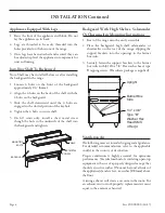
Installing Shelf To Backguard
Note: Shelf may be installed before or after installing
the backguard to the range.
. Loosen 4 bolts on the front of the backguard
approximately /4” (6mm).
2. Align the 4 holes on the back of the shelf with the
4 bolts on the backguard.
3. Slide the shelf downward until the 4 bolts are
engaged in the slotted portion of the keyhole.
4. Tighten the 4 bolts to secure shelf.
5. On 60” units only, install a sheet metal screw
though the hole in the underside of the shelf into
the backguard and tighten.
MOUNTING
BOLTS
BACKGUARD
SHELF
SHEETMETAL
SCREW
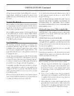
Backguard With High Shelves, Salamander
Or Cheesemelters Mounting Instructions
. Rear of the range must be easily accessible
2. Place the backguard, high shelf, salamander, or
cheesmelter on the rear of the range, slipping the
support brackets into the openings in the burner
box sides.
3. Securely fasten the support brackets to the burner
box sides with (4) #4 x 5/8” Hex washer head, type
B tapping screws. (Hardware package is supplied).
Upright
Burner Box
Side
1/4" x 3/4"
Type "B"
Washer Hex
Head SMS
4 Req'd
Ventilation Air
The following notes are intended to give general guidance.
For detailed recommendations, refer to the applicable
code(s) in the country of destination.
Proper ventilation is highly essential for optimum
performance. The ideal method of ventilating open-top
equipment is the use of a properly designed canopy that
should extend six inches (152 mm), beyond all sides of
the appliance(s) and six feet, six inches (1981mm) above
the floor.
A strong exhaust will create a vacuum in the room. For
an exhaust vent to work properly, replacement air must
equal to the amount exhausted.
INSTALLATION Continued
Содержание U36-6S
Страница 15: ...Part XXXXXXX 02 07 Page 15 NOTES...
Страница 16: ......