U.S. General 2575 Скачать руководство пользователя страница 6

SKU 02575 

For technical questions, please call 1-800-444-3353.


Page 6

AssEMBLY INsTRUCTIONs

Note:

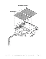
  For additional references to the parts listed below, refer to the 

Assembly Diagrams 

near the end of this manual.

To Assemble the Tires, Wheels, and Axle:

Insert one Hub (20) fully onto each end of the Axle (19).

1. 

BEARING PACKING INsTRUCTIONs:

2. 

  Read the following instructions; failure 

to read and obey all of the following instructions COMPLETELY will void the 

warranty and can result in damage to the trailer, property damage, or sERI-

OUs PERsONAL INJURY.


Whenever a hub is disassembled (if a hub on a new unit requires assembly or a hub 

is disassembled for maintenance), the following procedure MUST be followed.

Using a suitable solvent, thoroughly clean the bearings and the rest of the parts in 

a. 

the Hub assembly of all grease, dirt, metal shavings, or any other foreign object. 

The parts must be cleaned even if they are new or appear clean.

Allow all pieces to dry completely.

b. 

Make sure that your hands are thoroughly clean and the bearing packer (not 

c. 

included) is also thoroughly clean.
Place fresh, clean bearing grease in the packer.

d. 

With the grease-filled bearing packer in one hand and the bearing in the other, 

e. 

press the bearing into the grease, forcing the grease inside the slots in the 

bearing, continue doing this until every slot in the bearing is completely full of 

grease.
Be careful not to get any dirt or debris on any part of the assembly while you 

f. 

continue assembly.

Insert one Outer Bearing (21) into each Hub (20).  Then, insert one 3/4” Flat Washer 

3. 

(O) fully onto each end of the Axle (19).
Screw one Castle Nut (Q) fully onto each end of the Axle (19).  

4. 

NOTE:

 Do not 

overtighten

 the Castle Nut.  Make sure the Hub (20) turns freely.  Then insert one 

5/32” Cotter Pin (P) through each of the Castle Nuts, and bend each Cotter Pin to 

secure the Castle Nut in place.

Insert one Dust Cap (22) onto each of the two Castle Nuts (Q).  

5. 

NOTE:

 A rubber 

mallet (not included) may be required to firmly secure the Dust Caps onto the Castle 

Nuts.
Align the four mounting holes in a Tire & Wheel Assembly (23) with the four Lug 

6. 

Bolts on a Hub (20), and insert the Tire & Wheel Assembly onto the Hub.  Firmly 

secure the Tire & Wheel Assembly to the Hub, using four Wheel Nuts (S).  Then, 

repeat this Step for the remaining Tire & Wheel Assembly and Hub.

Содержание 2575

Страница 1: ...secured properly the ball could come loose while the trailer is in motion possibly causing property damage SERIOUS PERSONAL INJURY or DEATH Manual Revised 04j 07f 09b Diagrams within this manual may n...

Страница 2: ...acket and License Plate Bracket 10 To Attach the Tail Lights 10 To Attach the Trailer Beds 11 OPERATING INSTRUCTIONS 12 Tire information 13 Tire Terminology Glossary 13 Tire Markings 14 Tire Inflation...

Страница 3: ...2 Do not allow children to play on this product STORE IDLE EQUIPMENT 3 When not in use tools and equipment should be stored in a dry location to inhibit rust Always lock up tools and equipment and ke...

Страница 4: ...or which this equipment was designed It will do the job better and more safely at the capacity for which it was intended Do not modify this equipment and do not use this equipment for a purpose for wh...

Страница 5: ...T EXCEED 45 MILES PER HOUR WHEN TOWING THE TRAILER 8 Excess speed is an important cause of vehicle trailer accidents THE TAIL LIGHT BULBS SUPPLIED WITH THIS TRAILER ARE FOR A 12 VOLT 9 DC ELECTRICAL S...

Страница 6: ...is also thoroughly clean Place fresh clean bearing grease in the packer d With the grease filled bearing packer in one hand and the bearing in the other e press the bearing into the grease forcing th...

Страница 7: ...and one Nut B See Figure A RIGHT SIDE RAIL 1R REAR CROSS MEMBER 3 CROSS MEMBER 2 CROSS MEMBER 2 LEFT SIDE RAIL 1L RIGHT CONNECTING RAIL 8 TOW BAR 9 COUPLER 12 LEFT CONNECTING RAIL 7 SAFETY CHAIN 10 T...

Страница 8: ...ee Washers C and three Nuts B See Figure A Align the 7 three mounting holes located in the Left Connecting Rail 7 with the one mounting hole located in the Left Side Rail 1L one mounting hole located...

Страница 9: ...E For the remaining Spring 18 Front Spring Hanger 15F and Rear Spring Hanger 7 15R repeat Steps 5 and 6 Align the center mounting hole of a Spring Plate 16 with the center mounting hole 8 of a pre att...

Страница 10: ...e Rail 1R Then secure the Side Running Light to the Right Side Rail with two Self Tapping Screws J To Attach the Tail Light Bracket and License Plate Bracket Align 1 two of the mounting holes in a Tai...

Страница 11: ...holes in the Left Side Rail 1L and two mounting holes in the Right Side Rail 1R Secure the Trailer Bed to the Left and Right Side Rails with four Bolts A four Washers C and four Nuts B Align the 2 fou...

Страница 12: ...ing the Handle the Nut retaining plate holding the adjusting nut in place needs to be pressed back while the Nut is tightened After Nut is tightened the retaining plate needs to fit in place against t...

Страница 13: ...loaded vehicle weight means the sum of Curb weight a Accessory weight b Vehicle capacity weight and c Production options weight d Maximum tire width means the greater of either the linear distance be...

Страница 14: ...e where it was manufactured and the last four numbers represent the week and year that the tire was built For example the numbers 2107 mean the 21st week of 2007 Any other numbers used are marketing c...

Страница 15: ...r and others Maximum Permissible Inflation Pressure This number is the greatest amount of air pressure that should ever be put in the tire under normal driving conditions Tire Inflation and Load Limit...

Страница 16: ...at has been driven on Tires heat up while being driven on To check or fill to a tire s cold inflation the tire must have not been driven for more than a mile or two for at least three hours If you che...

Страница 17: ...e left and right tires should be switched This will cause the tires to wear more evenly and last longer Tire Balance and Alignment The tires need to be balanced to prevent vibration when driving This...

Страница 18: ...or binding of moving parts cracked bent or broken parts excessively worn Safety Chain damaged Tail Lights Side Running Lights Wiring Harness loose Lug Nuts loose Hitch connection and any other conditi...

Страница 19: ...T PARTS THERETO Note Some parts are listed and shown for illustration purposes only and are not available individually as replacement parts Parts List and DIAGRAMS Parts List Part Description Qty 1L L...

Страница 20: ...SKU 02575 For technical questions please call 1 800 444 3353 Page 20 Assembly Diagram A N B...

Страница 21: ...SKU 02575 For technical questions please call 1 800 444 3353 Page 21 Assembly Diagram B TRAILER BED X WASHER C NUT B BOLT A...

Страница 22: ...uestions please call 1 800 444 3353 Page 22 Wiring Diagram for Lights Note Some trailer tail lights will have two leads instead of three They connect to the harness leads the same way brown to brown c...

Страница 23: ...cidental or consequential damages so the above limitation of exclusion may not apply to you This warranty is expressly in lieu of all other warranties express or implied including the warranties of me...

Отзывы: