IQ LCD Display Kit – Instruction Sheet
105918-01
Page 3 of 12
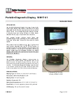
Portable Diagnostic Display
Installation
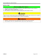
1. Turn off all power.
2. Place
Portable Diagnostic Display on top of boiler
.
3. Connect the
Portable Diagnostic Display
wiring harness to the boiler’s wiring harness. Note an additional wiring
harness is provided when attaching to Oil fired boilers other than the MPO-IQ. A matching connector can be found
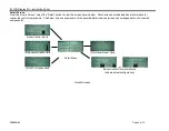
behind the boiler’s control panel on most boilers. See connections for different boilers below.
4. Turn Power On.
Boilers
Connection Example
ES2 Boiler,
Series 3 Boiler
ESC Boiler
MPO-IQ Oil Boiler.
Series 2
PVG
V8H
LEDV1
LE1
RSAH, RSA
V1 RO/FO
Checkout
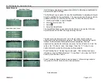
Check to make certain that the LCD display powers up. Allow the display to initialize. After initialization,
perform the following test:
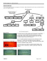
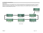
1. Select the Detail button. Ensure that installed components are shown. For example; IQ LWCO; IQ
Aquastat; IQ Reset Option Cards.
2. Select the Status button. Ensure that installed IQ Zone Panel status is shown.
3. If items do not appear on screen, check component installation and wiring.

